


Model 9110T NOx Analyzer Troubleshooting & Service
Teledyne Analytical Instruments 272
12.4. GAS FLOW PROBLEMS
The 9110T has two main flow paths, the sample flow and the flow of the ozone supply air. With IZS or
zero/span valve option installed, there is a third (zero air) and a fourth (span gas) flow path, but either
one of those is only controlled by critical flow orifices and not displayed on the front panel or stored to
the DAS.
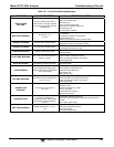
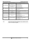
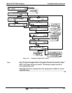
Flow is too high
Flow is greater than zero, but is too low, and/or unstable
Flow is zero (no flow)
When troubleshooting flow problems, it is essential to confirm the actual flow rate without relying on the
analyzer’s flow display. The use of an independent, external flow meter to perform a flow check as
described in Section 11.3.12.3 is essential. Refer to the pneumatic flow diagrams as needed for
reference.
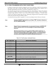
12.4.1. ZERO OR LOW FLOW PROBLEMS
12.4.1.1. Sample Flow is Zero or Low
The 9110T does not actually measure the sample flow but rather calculates it from a differential pressure
between sample and vacuum manifold. On flow failure, the unit will display a SAMPLE FLOW
WARNING on the front panel display and the respective test function reports XXXX instead of a value
“0”. This message applies to both a flow rate of zero as well as a flow that is outside the standard range
(350-600 cm³/min).
If the analyzer displays XXXX for the sample flow, confirm that the external sample pump is operating
and configured for the proper AC voltage.
Whereas the 9110T can be internally configured for two different power regimes (100-120 V and
220-240 V, either 50 or 60 Hz), the external pump is physically different for each of three power
regimes (100 V / 50 Hz, 115 V / 60 Hz and 230 V / 50 Hz).
If the pump is not running, use an AC Voltmeter to ensure that the pump is supplied with the proper
AC power. If AC power is supplied properly, but the pump is not running, replace the pump.
Note Sample and vacuum pressures mentioned in this chapter refer to
operation of the analyzer at sea level. Pressure values need to be
adjusted for elevated locations, as the ambient pressure decreases by
about 1 in-Hg per 300 m / 1000 ft.
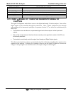
If the pump is operating but the unit reports a XXXX gas flow, take the following three steps:
1. Check for actual sample flow.
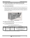
To check the actual sample flow, disconnect the sample tube from the sample
inlet on the rear panel of the instrument.
Ensure that the unit is in basic SAMPLE mode.
Place a finger over the inlet and see if it gets sucked in by the vacuum or, more
properly, use a flow meter to measure the actual flow.