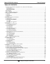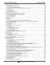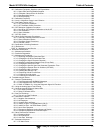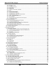
Model 9110T NOx Analyzer Table of Contents
Teledyne Analytical Instruments 18
TABLES
Table 1-1. Analyzer Options .......................................................................................................................... 24
Table 2-2: Software Settings for EPA Equivalence....................................................................................... 28
Table 3-1: Ventilation Clearance ................................................................................................................... 32
Table 3-5: Analog Output Pin Assignments .................................................................................................. 43
Table 3-6: Status Output Pin Assignments ................................................................................................... 45
Table 3-7: Control Input Pin Assignments .................................................................................................... 46
Table 3-8: NIST-SRM's Available for Traceability of NO
x
Calibration Gases ................................................ 57
Table 3-9: Zero/Span Valves Operating States OPT 50A ............................................................................ 65
Table 3-10: Valve Operating States OPT 50B installed .................................................................................. 69
Table 3-11: Internal Span Gas Generator Valve Operating States OPT 50G ................................................ 71
Table 3-12: Possible Warning Messages at Start-Up ..................................................................................... 76
Table 4-1: Analyzer Operating Modes .......................................................................................................... 88
Table 4-2: Test Functions Defined ................................................................................................................ 88
Table 4-3: Warning Messages Defined ......................................................................................................... 91
Table 4-4: Primary Setup Mode Features and Functions ............................................................................. 93
Table 4-5: Secondary Setup Mode Features and Functions ........................................................................ 93
Table 5-1: IND Mode Analog Output Assignments ....................................................................................... 99
Table 5-2: Password Levels ........................................................................................................................106
Table 5-3: Variable Names (VARS) ............................................................................................................112
Table 5-4: Diagnostic Mode (DIAG) Functions ...........................................................................................114
Table 5-5: DIAG - Analog I/O Functions .....................................................................................................117
Table 5-6: Analog Output Voltage Range Min/Max ....................................................................................119
Table 5-7: Voltage Tolerances for the TEST CHANNEL Calibration ..........................................................123
Table 5-8: Current Loop Output Check .......................................................................................................127
Table 5-9: Test Channels Functions available on the 9110T’s Analog Output ...........................................132
Table 6-1: COMM Port Communication Modes ..........................................................................................135
Table 6-2: Ethernet Status Indicators .........................................................................................................140
Table 6-4: RS-232 Communication Parameters for Hessen Protocol ........................................................151
Table 6-5: Teledyne's Hessen Protocol Response Modes .........................................................................154
Table 6-6: Default Hessen Status Flag Assignments .................................................................................159
Table 7-1: Front Panel LED Status Indicators for DAS ...............................................................................163
Table 7-2: DAS Data Channel Properties ...................................................................................................164
Table 7-3: DAS Data Parameter Functions ................................................................................................172
Table 8-1: Terminal Mode Software Commands ........................................................................................186
Table 8-2: Teledyne API's Serial I/O Command Types ..............................................................................186
Table 9-1: IZS Option Valve States with CAL_ON_NO
2
Turned ON ..........................................................203
Table 9-2: AUTOCAL Modes ......................................................................................................................213
Table 9-3: AutoCal Attribute Setup Parameters ..........................................................................................214
Table 9-4: Example AutoCal Sequence ......................................................................................................215
Table 9-5: Calibration Data Quality Evaluation ...........................................................................................219
Table 10-1: Activity Matrix for EPA Calibration Equipment and Supplies .....................................................222
Table 10-2: Definition of Level 1 and Level 2 Zero and Span Checks .........................................................224
Table 10-3: Activity Matrix for Data Quality ...................................................................................................233
Table 11-1: 9110T Maintenance Schedule ...................................................................................................240
Table 11-2: Predictive Uses for Test Functions ............................................................................................241
Table 12-1: Front Panel Warning Messages ................................................................................................264
Table 12-2: Test Functions - Indicated Failures ............................................................................................266
Table 12-3: Test Channel Outputs as Diagnostic Tools ...............................................................................269
Table 12-4: Relay PCA Watchdog LED Failure Indications ..........................................................................270
Table 12-5: Relay PCA Status LED Failure Indications ................................................................................271
Table 12-6: DC Power Test Point and Wiring Color Codes ..........................................................................284
Table 12-7: DC Power Supply Acceptable Levels ........................................................................................284
Table 12-8: Relay PCA Control Devices .......................................................................................................285
Table 12-9: Analog Output Test Function - Nominal Values Voltage Outputs .............................................286
Table 12-10: Status Outputs Check ................................................................................................................288
Table 12-11: 9110T Control Input Pin Assignments and Corresponding Signal I/O Functions ......................288


