


7
Using The Timing Analyzer
Introduction In this chapter you will learn how to use the timing analyzer by setting up
the logic analyzer to make a simple measurement. We give you the
measurement results as actually measured by the logic analyzer, since you
may not have the same circuit available.
The exercise in this chapter is organized in a task format. The tasks are
orderedinthesamewayyouwillmostlikelyusethemonceyoubecome
an experienced user. The steps in this format are both numbered and
lettered. The numbered steps state the step objective. The lettered steps
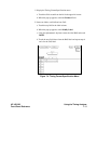
explain how to accomplish each step objective. There is also an example
of each menu after it has been properly set up.
How you use the steps depends on how much you remember from
chapters 1 through 5. If you can set up each menu by just looking at the
menu picture, go ahead and do so. If you need a reminder of what steps
you need to perform, follow the numbered steps. If you still need more
information about "how," use the lettered steps.
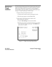
Problem Solving
with the
Timing Analyzer
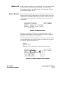
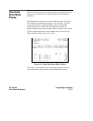
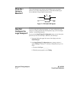
In this exercise, assume you are designing a dynamic RAM memory
(DRAM) controller and you must verify the timing of the row address
strobe (RAS) and the column address strobe (CAS). You are using a 4116
dynamic ram and the data book specifies that the minimum time from
whenLRASisasserted(goeslow)towhenLCASisnolongerasserted
(goes high) is 250 ns. You could use an oscilloscope but you have an HP
16500A/510B on your bench. Since the timing analyzer will do just fine
when you don’t need voltage parametrics, you decide to go ahead and use
the logic analyzer.
HP 16510B Using the Timing Analyzer
Front-Panel Reference 7 - 1