


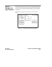
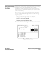

Now it’s time to look at the hardware to see if it is causing incorrect data
when the microprocessor reads this memory address. You decide you want
to see what is happening on the address and data buses during this routine
in the time domain.
In order to see the time domain, you need the timing analyzer.
What Additional
Measurements
Must I Make?
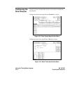
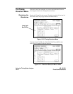
Since the problem exists during the routine that starts at address 8930, you
decide you want to see the timing waveforms on the address and data bus
when the routine is running. You also want to see the control signals that
control the read cycle. You will then compare the waveforms with the
timing diagrams in the 68000 data book.
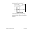
Your measurement, then, requires verification of:
• correct timing of the control signals
• stable addresses and data during the memory read
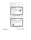
The control signals you must check are:
• system clock
• address strobe (AS)
• lower and upper data strobes (LDS and UDS)
• data transfer acknowledge (DTACK)
• read/write (R/W)
HP 16510B Using the Timing/State Analyzer
Front-Panel Reference 12-7