


The Timing
Waveform Menu
The timing waveform menu differs from the other menus you have used
so far in this exercise. Besides displaying the acquired data, it has menu
fields that you use to change the way the acquired data is displayed and
fields that give you timing answers. Before you can use this menu to find
answers, you need to know some of the special symbols and their
functions. The symbols are:
• The green and yellow dotted lines
• The red dotted line
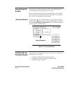
The Green and
Yellow Dotted
Lines
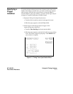
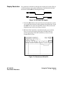
The X and O markers are green and yellow vertical dotted lines
respectively. You can use them to find your answer. You place them on
the points of interest on your waveforms and the logic analyzer displays
the time between the markers. The X and O markers will be in the center
of the display when X to trig(ger) and O to trig(ger) are both 0.000 s
(see example below).
The X marker displayed is green and the O marker displayed is yellow.
The trigger marker is red.
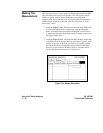
The Red Dotted
Line
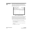
The red vertical dotted line indicates the trigger point you specified in the
Timing Trace Specification menu. The red dotted line is at center screen
and is superimposed on the negative-going edge of the RAS signal.
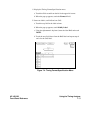
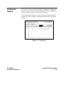
Configuring the
Display
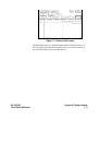
Now that you have acquired the RAS and CAS waveforms, you need to
configure the Timing Waveforms menu for best resolution and to obtain
your answer.
Using the Timing Analyzer HP 16510B
7 - 10 Front-Panel Reference