


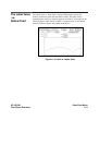

Connecting the
Probes
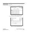
At this point, if you had a target system with a 68000 microprocessor, you
would connect the logic analyzer to your system. Since you have assigned
labels ADDR and DATA, you would hook the probes to your system
accordingly.
• Pod1probes0through15tothedatabuslinesD0throughD15
• Pod2probes0through15totheaddressbuslinesA0throughA15
• Pod 3 probes 0 through 7 to the address bus lines A16 through A23
• Pod 1, CLK (J clock) to the address strobe (LAS)
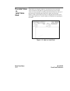
Acquiring the
Data
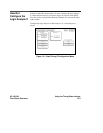
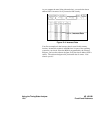
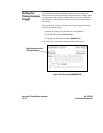
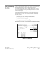
Since you want to capture the data when the microprocessor sends address
8930 on the bus, you press the Run field to arm the state analyzer. If the
microprocessor sends address 8930, it will trigger the state analyzer and
switch the display to the State Listing.
We’ll assume this is what happens in this example.
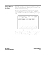
Finding the
Problem
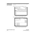
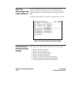
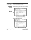
You look at this listing to see what the data is in states +0000 through
+0004. You know your routine is five states long.
The 68000 does address location 8930 so you know that the routine is
addressed. Now you need to compare the state listing with the following
correct addresses and data:
+0000 008930 B03C
+0001 008932 61FA
+0002 008934 67F8
+0003 008936 B03C
+0004 00892E 61FA
HP 16510B Using the Timing/State Analyzer
Front-Panel Reference 12-5