


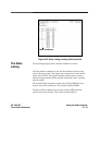
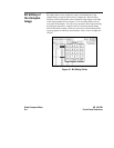

Summary You have just learned how to make a simple state measurement with the
HP 16510B Logic Analyzer. You have:
• specified a state analyzer
• learned which probes to connect
• assigned pods 1, 2, and 3
• assigned labels
• assigned bits
• specified the J clock
• specified a trigger condition
• acquired the data
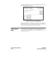
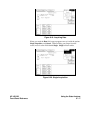
• interpreted the State Listing
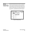
You have seen how easy it is to use the state analyzer to capture the data
on the address and data buses. You can use this same technique to capture
and display related data on the microprocessor status, control, and various
strobe lines. You are not limited to using this technique on
microprocessors. You can use this technique anytime you need to capture
data on multiple lines and need to sample the data relative to a system
clock.
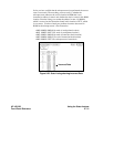
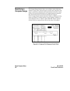
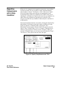
The next chapter teaches you how to use the logic analyzer as an
interactive timing and state analyzer. You will see a simple measurement
that shows you both timing waveforms and state listings and how they are
correlated.
Using the State Analyzer HP 16510B
8 - 22 Front-Panel Reference