


Demultiplexing is done on the data lines of the specified pod to read only
the lower eight bits. This is two phase clocking, with the Master Clock
following the Slave Clock. The analyzer first looks for the clocking
arrangement that you specify in the Slave Clock. When it sees that, the
analyzer clocks the data present on bits 0-7 of the pod, then waits for the
clocking arrangement that you specify in the Master Clock.Whenitsees
that clocking arrangement, it again clocks the data present on bits 0-7 of
the pod. The upper eight bits of the pod are ignored and don’t need to be
connected to your system.
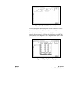
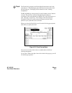
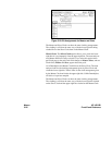
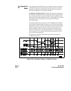
Notice that the bit numbers that appear above the bit assignment field have
changed. The bits are now numbered 7....07....0 instead of 15....87....0.
This helps you set up the analyzer to clock the right information at the
right time.
The address/data lines AD0-AD7 on the 8085 microprocessor are an
example for Demultiplex. During part of the operating time the lines have
an address on them, and during other times they have data on them.
Connect the lower eight bits of one of the pods to these eight lines and set
the Slave and Master Clocks for the pod such that they clock the data and
the address at the proper time.
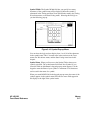
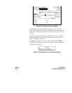
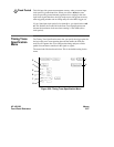
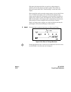
In this example, you may choose to assign the bits in the State Format
Specification menu similar to that shown in the following figure. In this
case you would want to clock the address with the Slave Clock and the
data with the Master Clock.
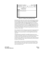
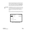
Figure 5-27. Master Clock and Slave Clock
HP 16510B Menus
Front-Panel Reference 5-25