


Connecting the
Probes
At this point, if you had a target system with a 4116 DRAM memory IC,
you would connect the logic analyzer to your system.
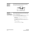
Since you will be assigning Pod 1 bit 0 to the RAS label, you hook Pod 1
bit 0 to the memory IC pin connected to the RAS signal. You hook Pod 1
bit 1 to the IC pin connected to the CAS signal.
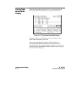
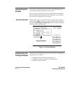
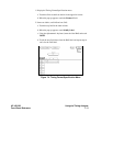
Activity Indicators When the logic analyzer is connected and your target system is running,
you will see two at the right-most end (least significant bits) of the Pod 1
fieldintheState/Timing E Configuration menu. This indicates the RAS
and CAS signals are transitioning.
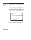
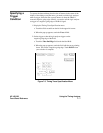
Configuring the
Timing Analyzer
Now that you have configured the system, you are ready to configure the
timing analyzer. You will be:
• Creating two names (labels) for the input signals
• Assigning the channels connected to the input signals
• Specifying a trigger condition
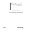
Activity Indicators
Figure 7-3. Activity Indicators
Using the Timing Analyzer HP 16510B
7 - 4 Front-Panel Reference