


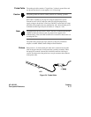


Signal Line
Loading
Any signal line you intend to probe must be able to supply a minimum of
600 mV to the probe tip, which has an input impedance of 100 kΩ shunted
by 8 pF. If the signal line is incapable of this, you will not only have an
incorrect measurement but the system under test may also malfunction.
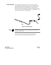
Maximum Probe
Input Voltage
The maximum input voltage of each probe is ± 40 volts peak.
Pod Thresholds There are two preset thresholds and a user-definable pod threshold for
each pod. The two preset thresholds are ECL (−1.3 V) and TTL
(+1.6 V). The user-definable threshold can be set anywhere between
−9.9 volts and + 9.9 volts in 0.1 volt increments.
The pod thresholds of pods 1, 2, and 3 can be set independently. The pod
thresholds of pods 4 and 5 are slaved together; therefore, when you set the
threshold on either pod 4 or 5, both thresholds will be the same.
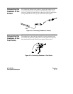
Connecting the
Logic Analyzer
to the Target
System
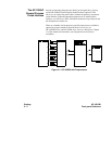
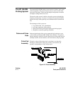
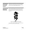
There are four ways you can connect the logic analyzer to your target
system as previously mentioned at the beginning of this chapter: the
probes (general purpose probing); the HP 10320C User-definable
Interface; the HP 10269C with microprocessor specific preprocessor
modules; and direct connection to a 20 pin 3M
Series type header
connector using the optional termination adapter (HP Part No.
01650-63201).
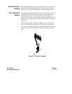
Since the probe interface hook-ups are microprocessor specific, they will
be explained in their respective operating notes. The rest of this chapter
is dedicated to general purpose probing with the HP 16510B probes.
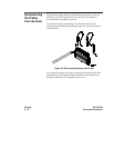
Probing HP 16510B
2 - 8 Front-panel Reference