


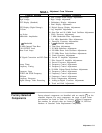
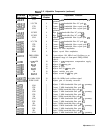
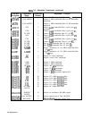
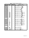
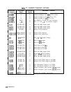

‘able
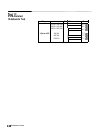
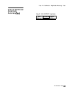
3-l.
Adjustment Cross Reference
Function Adjusted
Low Voltage
High Voltage
CRT Display (Standard)
CRT Display (Digital Storage)
IF Gains
Log Scales
Bandwidth Amplitudes
3
dB
Bandwidth
10 MHz Internal Time Base
CAL OUTPUT Level
Phase Lock Loops
Adjustment Procedure
1. Low Voltage Power Supply Adjustments
2. High Voltage Adjustment
3. Preliminary Display Adjustment
4. Final Display Adjustments
25. Digital Storage Display Adjustments
5. Log Amplifier Adjustments
10. Step Gain and 18.4 MHz Local Oscillator Adjustments
6. Video Processor Adjustments
7. 3 MHz Bandwidth Filter Adjustments
8. 21.4 MHz Bandwidth Filter Adjustments
11. Down/Up Converter Adjustments
9. 3
dB Bandwidth Adjustments
12. Time Base Adjustments
13. 20 MHz Reference Adjustments
14. 249 MHz Phase Lock Oscillator Adjustments
15. 275 MHz Phase Lock Oscillator Adjustments
22. Comb Generator Adjustments
RF Signal Conversion and RF Gains 16. Second IF Amplifier Adjustments
17. Pilot Second IF Amplifier Adjustments
19. Second Converter Adjustments
Sweep Times
18. Frequency Control Adjustments
Frequency Tuning 18. Frequency Control Adjustments
20. 50 MHz Voltage-Tuned Oscillator Adjustments
Frequency Span
18. Frequency Control Adjustments
START and STOP Frequency
18. Frequency Control Adjustments
FM Span
18. Frequency Control Adjustments
Frequency Response
21. Slope Compensation Adjustment
Digital Storage Video Processing
23. Analog-to-Digital Converter Adjustments
24. Track and Hold Adjustments
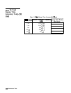
Factory-Selected
Components
Factory-selected components are identified with an asterisk
(*)
on the
schematic diagram. For most components, the range of their values
and functions are listed in Table 3-3, Factory- Selected Components.
Part numbers for selected values are located in
Table
3-4, HP Part
Numbers of Standard Value Replacement Components.
Adjustments 3-3