


13. 20 MHz Reference Adjustments
Procedure
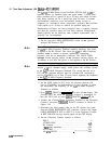
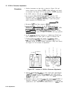
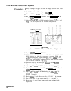
1. Position instrument on right side as shown in Figure 3-56 and
remove bottom cover. Remove
Al6
20 MHz Reference and install
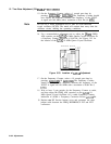
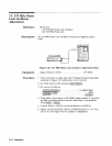
on extenders. See Figure 3-57 for the location of
Al6
components.
2. Set LINE switch to ON and press (INSTR PRESET).
3. Set rear-panel FREQ REFERENCE INT/EXT switch to INT.
Disconnect cable 2 (red) from
A16Jl.
Connect power meter to
output of Time Base
(A27Jl)
using cable 2 (red). Note power
meter indication for reference later.
dBm
4. Reconnect
A27
Time Base output to
A16Jl.
5.
JumDer
A16TP4
to Ground. Set the HP
8566A/B
Spectrum
Analyzer to [CENTER FREQUENCY) 20 MHz, [FREQUENCY SPAN) 1 MHz,
CREFERENCE
LEVEL)
+20
dBm, and
(RES]
100 kHz. Connect
A16J3 to RF INPUT of HP
8566A/B
Soectrum
Analyzer and set
[REFERENCE
LEVEL)
to place of signal at reference line (top graticule
line).
6. Set HP
8566A/B
Spectrum Analyzer to 1 dB/division SCALE and
reset reference level to place peak of signal at reference line.
7. Connect DVM to A16TPl and ground to
A22
TP12.
Adjust
Al6
COMB DRIVE
A16R31
for DVM indication of > + 0.1 V dc.
Disconnect DVM. (If DVM remains connected, it may load circuit.)
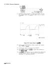
See Figure 3-57 for location of adjustment.
Al6
20MHz
REFERENCE
\,
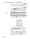
Figure 3-57. Location of 20 MHz Reference Adjustments
8. Adjust
Al6
DOUBLER A16Tl to lower signal peak approximately
3
dB.
Adjust
Al6
CENTER FREQ
A16Cll
to peak signal on HP
8566A/B
Spectrum Analyzer display. Next, adjust
Al6
DOUBLER
A16Tl for signal peak.
9. Disconnect cable 2 (red) from
A16Jl
and connect 500 OUTPUT of
frequency synthesizer to
A16Jl.
Set FREQUENCY of frequency
synthesizer to 10.17 MHz and set AMPLITUDE to + 3 dBm. Set HP
3-104 Adjustments