


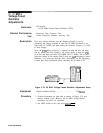
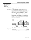
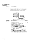

22. Comb Generator Adjustments
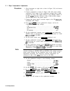
a typical comb tooth display. See Figure 3-83 for location of
adjustments.
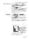
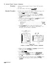
14. The majority of the comb teeth should be above the -30
dBm
Display Line. No comb teeth should exceed -22 dBm, and no
comb teeth should be less than -36 dBm.
15. If unable to adjust comb teeth as described in previous steps,
proceed with the next step. If comb teeth are adjusted properly,
do not perform the adjustments in the following steps. Skip to
step 21.
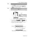
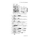
16. Adjust
A23A6
COMB PEAK
A23A6L2
for maximum amplitude of
comb teeth. See Figure 3-83 for location of adjustment.
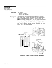
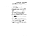
17. If the highest-frequency comb tooth is too low
(c-36
dBm),
remove screws from cover of
A23A6
Comb Generator and lift
cover from housing, being careful not to break wire connections
to internal circuit. It will be necessary to hold cover away from
housing while performing the following adjustment.
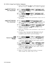
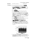
18. Adjust
A23A6
HF PEAK
A23A6C7
for maximum amplitude of the
highest-frequency comb tooth displayed ( comb tooth to far right
of CRT). See Figure 3-84 for location of adjustment.
19. Replace cover on
A23A6
and install screws.
20. Go back to step 12 and proceed with adjustments.
21. Remove cable from between
A23A65J2 and A23A3J 1 and
reconnect instrument cables to connectors from which they were
removed.
3-138 Adjustments