


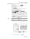
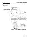
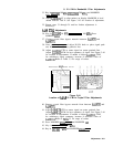

8. 21.4 MHz Bandwidth Filter Adjustments
8. 21.4 MHz
Bandwidth Filter
Adjustments
Reference
Related Performance
Tests
Description
IF-Display Section
A4A4
Bandwidth Filter
A4A8
Attenuator-Bandwidth Filter
IF Gain Uncertainty Test
Resolution Bandwidth Switching Uncertainty test
Resolution Bandwidth Selectivity Test
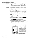
First the LC Filters (100 kHz to 3 MHz bandwidths) on the
A4A4
Bandwidth Filter are adjusted. The crystal filter poles (3 kHz to 30
kHz bandwidths) are then adjusted for center and symmetry by
bypassing all but one pole at a time and adjusting the active pole.
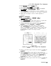
Next, the LC filters and the crystal filter poles on the
A4A8
Attenuator-Bandwidth Filter are adjusted in the same manner as on
the
A4A4
Bandwidth Filter.
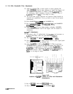
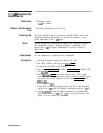
Last, the 10 dB and 20
dB
attenuators on the
A4A8
Attenuator-
Bandwidth Filter are adjusted for the proper amount of attenuation.
This is done by connecting the CAL OUTPUT signal to the RF INPUT
through two step attenuators, keying in the necessary reference level
to activate the 10
dB
and the 20
dB
control lines, adjusting the step
attenuators to compensate for the attenuation, and adjusting the
attenuators for the proper amount of attenuation.
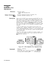
SPECTRUM ANALYZER
I
DIGITAL VOLTMETER
rm
1OdB
STEP
IdH STEP
ATTENUATOR ATTENUATOR
Figure 3-40. 21.4 MHz Bandwidth Filter Adjustments Setup
Adjustments 3-77