


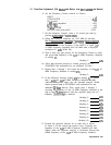
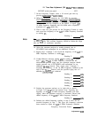

13. 20 MHz Reference Adjustments
8566AB
Spectrum Analyzer (CENTER FREQUENCY_) to 20.34 MHz and
SCALE to 10 dB/division.
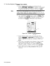
10. Adjust
Al6
20.34 MHz NULL
A16C12
for minimum 20.34 MHz
signal at A16J3 as indicated by HP
8566A/B
Spectrum Analyzer
display. With signal
nulled,
the plates of the NULL adjustment
capacitor should be meshed approximately halfway. If fully
meshed or fully unmeshed, a circuit malfunction is indicated.
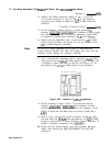
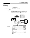
11. Disconnect frequency synthesizer from
A16Jl
and reconnect cable
2 (red) to
A16Jl.
Connect power meter to rear-panel INT REF
OUT connector.
12. Power meter indication should be no more than 5
dB
less than
that noted in step 3
(A27
Time Base output).
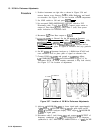
13. Disconnect
A16TP4
from ground. Connect power meter to A16J3.
14. Adjust
Al6
COMB DRIVE
A16R31
for power meter indication of
+ 10.0 dBm
+l.O
dB.
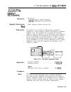
15. Connect power meter to A16J4 through cable 3 (orange). Power
meter indication should be at least -15 dBm. Reconnect cable 3
(orange) to A6J2.
16. Connect power meter to A16J5 through cable 4 (yellow). Power
meter indication should be at least -10 dBm. Reconnect cable 4
(yellow) to
A8Jl.
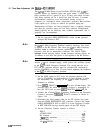
17. On the oscilloscope, key in
[RECALL)
[mj
to perform a soft
reset.
18. Connect
the channel 1 probe to the oscilloscope’s rear panel
PROBE COMPENSATION AC CALIBRATOR OUTPUT connector.
Press [AUTO SCALE). Adjust the channel 1 probe for an optimum
square wave display on the oscilloscope.
19. Connect oscilloscope with the HP
10432A
probe to
A16TP3
and
the ground to the analyzer’s chassis ground.
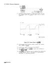
20. Set the oscilloscope controls as follows:
Press
m):
Channel 1 . . . . . . . . . . . . . . . . . . . . . . . . . . . . . . . . . . . . ..on
amplitude scale . . . . . . . . . . . . . . . . . . . . . . . . . . .
1V
/ div
offset
. . . . . . . . . . . . . . . . . . . . . . . . . . . . . . . . . . . . . . . ..OV
coupling
. . . . . . . . . . . . . . . . . . . . . . . . . . . . . . . . . . . . . ..dc
probe . . . . . . . . . . . . . . . . . . . . . . . . . . . . . . . . . . . . . . . .
1O:l
Channel2
. . . . . . . . . . . . . . . . . . . . . . . . . . . . . . . . . . . . . off
Channel4
. . . . . . . . . . . . . . . . . . . . . . . . . . . . . . . . . . . . . off
Press
ITRIG):
EDGE TRIGGER . . . . . . . . . . . . . . . . . . . . . . . . trig’d auto
source
. . . . . . . . . . . . . . . . . . . . . . . . . . . . . . . . . . . . . . . . . . 1
level . . . . . . . . . . . . . . . . . . . . . . . . . . . . . . . . . 800 mv edge
Press
@iKZi%BASE_):
time scale . . . . . . . . . . . . . . . . . . . . . . . . . . . . . . . . . . . 20 ns
delay. . . . . . .
.._.............................
40ns
reference
. . . . . . . . . . . . . . . . . . . . . . . . . . . . . . . . . ..CNTR
Press
@KKK]:
connect dots
. . . . . . . . . . . . . . . . . . . . . . . . . . . . . . . . . . . on
DISPLAY . . . . . . . . . . . . . . . . . . . . . . . . . . .......... AVG
Adjustments
3-105