


2. High-Voltage Adjustment (SN 3001A and Below)
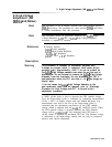
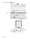
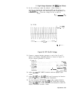
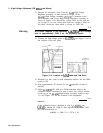
34. On the oscilloscope, adjust the channel 1 offset voltage as
necessary to measure the peak-to-peak CRT cut-off voltage, V,,,
at AlA3TP5. See Figure 3-9. This peak-to-peak voltage should be
between 45-75
V,.,.
Note this voltage for use in step 39.
1
10.0
V/div
offset:
60.00 v
10.00
:
1 dc
-250.000
us
0.00000
s
250.000
us
50.0
us/dlv
1
f
75.00 v
Figure 3-9. CRT Cut-Off Voltage
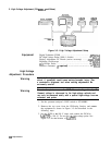
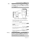
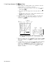
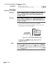
35. Connect a separate function generator to each of the X and Y
inputs of the Display Adjustment Board, as shown in Figure 3-5.
Set the function generators as follows:
X input Jl:
frequency
. . .. . . .. . . . . . . . . . . .. . . . . . . . .500
kHz
wave . .
amplitude
Y input
52:
frequency
.
.
.
.
.
.
.
.
.
.
.
1 kHz
wave .
.
.
.
.
.
.
.
.
amplitude
36. Adjust
AlA2R35 INT LIMIT clockwise until the display is just
visible.
37. Adjust
AlA4R7 POS,
AlA5R7
POS, and if necessary the function
generator
de
offsets for a full-screen illumination.
38. Set the front-panel INTENSITY control fully counter-clockwise,
and, if it is not sealed, adjust
AlA2R5 INT GAIN fully clockwise.
Adjust AlA2R35 INT LIMIT just below the threshold at which the
display illumination becomes visible.
Adjustments 3-35