


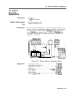

19. Second Converter Adjustments
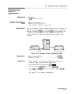
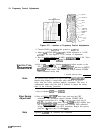
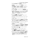
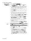
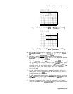
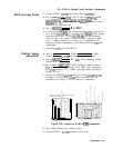
Figure 3-74. Typical PILOT
2ND
IF
Bandpass
(SHIFT t)
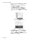
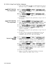
Figure 3-75. Typical PILOT
2ND
IF
Bandpass
(SHIFT
1)
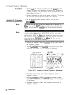
42. Key in
[*]
0)
u
and note amplitude of signal. Key in
ISHIFT)
@a
T
and note amplitude of the
bandpass
signal peak.
43. Continue to key in
[SHIFT]
0)
u then
a
T
while adjusting
A23A3Z8
for maximum amplitude and the same amplitude in both
states of the Second LO l
tcO.25
dB.
44. Check the
bandpass
at the 3
dB
points for both the
2ND
LO
1
and
1.
On the scalar network analyzer, press
(CURSORJ
Max. Press
cursor A (ON) and set the cursor at the -3
dB
point fO.l
dB.
Press
cursor A, cursor A, and set the cursor to the corresponding -3
dB
point on the opposit side of the signal. The cursor should now
read 0 fO.l
dB.
45. On the synthesized sweeper, press
Irvr3)
and place the marker on
either cursor A. Press
(M4),
and place the marker on the cursor A
on the opposite side of the trace.
46. On the synthesized sweeper, press
[Morn),
and read the
bandpass
(M3
-
M4)
shown on the ENTRY DISPLAY. Press
[Morn)
OFF. See
Figure 3-74 and Figure 3-75.
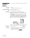
47. Disconnect the detector from cable 80 (gray/black) and connect
cable 92 (white/red) from A23A3J5
(2ND
IF) to the scalar network
analyzer’s A input.
Adjustments 3-127