


3. Preliminary Display Adjustments (SN 3004A and Above)
29. Set the oscilloscope controls as follows:
Press
(CHAN]:
Channel 1 . . . . . . . . . . on
amplitude scale . . . . . . .
.8.00 V/div
Press
@KiX-].
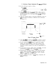
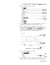
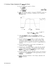
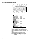
30. Adjust the spectrum analyzer’s front-panel INTENSITY control for
50V
peak-to-peak (8 divisions) as indicated on the oscilloscope.
See Figure 3-29.
hf
running
-125.000
ns
1.
125.000
ns
375.000~"s
50.0
ns/div
1
f
50.00 v
Figure 3-29.
5OV,.,
Signal
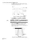
31. Adjust AlA2R308 HF GAIN and AlA2C307 for minimum
overshoot on rise and minimum rise and fall times of the pulse
waveform.
32. Use the oscilloscope
Intav)
markers to measure the risetime,
falltime, and percent overshoot of the pulse waveform. Rise
and falltimes should be less than 50 ns and 90 ns respectively.
Overshoot on the rise should be less than 5% (approximately 0.4
divisions).
33. Set the spectrum analyzer’s LINE switch to STANDBY and
reconnect the cable to
AlA2J5.
34. Disconnect the oscilloscope channel 1 probe from the spectrum
analyzer. Remove the Display Adjustment PC board from the
A3A2
slot, and reinstall the
A3A2
Intensity Control Assembly.
Replace the
A3
Section cover and cables.
35. Reconnect the black connector with three wires (8, 98, and 96) to
AlA2J5,
and set AlA2R319 INT GAIN approximately two-thirds
clockwise.
36. Perform Adjustment Procedure 4 Final Display Adjustment (SN
3004A
and Above).
3-58 Adjustments