


22. Comb
Generator
Adjustments
Reference
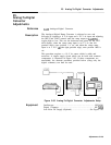
RF Section:
A23
RF Converter
Al6
20 MHz Reference
Description
The output of the Pilot First Converter is connected to the signal
input of the Second Converter. This allows the comb teeth from the
A23A6
Comb Generator to be displayed on the CRT display. The
phase lock flags are disabled, using a shift key function to prevent the
instrument from “locking up” due to the phase lock loops being open.
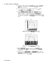
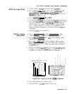
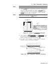
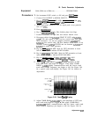
A display line is placed on the CRT at the level to which the comb
teeth are to be adjusted. the comb teeth are adjusted for best overall
flatness and to the proper amplitude.
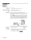
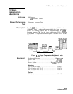
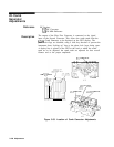
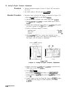
R31
COMB DRIVE
A23A6
COMB
(
;ENt
\
IRATOR
I
I
i
A6C7
HF PEAK
(Benenth
Cover)
A612
COMB PEAK
/
A4A2RE
COMB BIAS
Figure 3-83. Location of Comb Generator Adjustments
3-136 Adjustments