


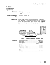

19. Second Converter Adjustments
48. Disconnect cable connected to A23A3J2 and connect to
A23A3Jl
(1ST
IF IN). Reconnect semi-rigid cable to A23A3J2 that was
disconnected in step 36.
49. Set the synthesized sweeper’s
a
for 2052.5 MHz
ho.1
MHz.
Adjust
a
to center the
bandpass
signal.
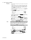
50. Adjust
A23A3
Zl,
22,
23,
and
L2
for best
bandpass
shape and
flatness at maximum amplitude of signal displayed on Scalar
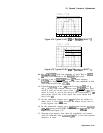
network analyzer. A typical properly-adjusted
bandpass
filter
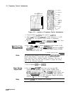
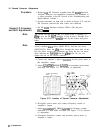
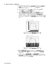
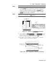
response is shown in Figure 3-76 and Figure 3-77. See Figure 3-73
for location of adjustments. The
bandpass
response should be
222
MHz.
1i
i i
i ii i I
Figure 3-76. Typical
Bandpass
(SHIFT
T)
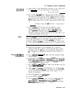
Figure 3-77. Typical
Bandpass
(SHIFT
1)
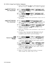
51.
Keyin=@)
u and note amplitude of the
bandpass
signal
peak. Key in (SHIFT)
a
T
and note amplitude of the
bandpass
signal peak.
52. Continue to key in
ISHIFT)
@j u then
m
a
T
while adjusting
A23A3Z4
for maximum amplitude and the same amplitude in both
states of the Second LO
fcO.1
dB.
3-128 Adjustments