


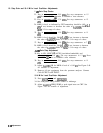

10. Step Gain and 18.4 MHz Local Oscillator Adjustments
1
dB
Gain Step Checks
22. Key in [REFERENCE LEVEL) -19.9 dBm. Set step attenuators to 15
dB.
Press MARKER
@
twice to establish a new reference.
23. Key in (REFERENCE LEVEL) -17.9 dBm. Set step attenuators to 13
dB.
24. MKR A level, as indicated by CRT annotation, should be .OO
f0.5
dB.
If not, increase or decrease the value of
A4A5R86.
Refer to
‘Ihble
3-3 for range of values.
25. Key in (REFERENCE LEVEL) -15.9 dBm. Set step attenuators to 11
dB.
26. MKR A level should be .OO
ho.5
dB.
If not, increase or decrease
the value of
A4A5R70.
Refer to Table 3-3 for range of values.
27. Key in [REFERENCE LEVEL) -11.9 dBm. Set step attenuators to 7
dB.
28. MKR A level should be .OO
ho.5
dB.
If not, increase or decrease
the value of
A4A5R62.
Refer to
‘Ihble
3-3 for range of values.
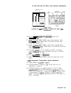
.l
dB
Gain Step Adjustment
29. Key in LIN, (SHIFT) * (AUTO] (resolution bandwidth), and
(REFERENCE LEVEL) -19.9 dBm. Set step attenuators to 13
dB.
Press
MARKER
(nl
twice to establish a new reference.
30. Key in [REFERENCE LEVEL) -18.0 dBm. Set step attenuators to 11
dB.
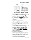
31. Adjust
A4A5R51
VR for MKR A level of + 0.10
dB.
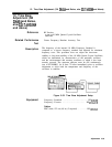
See Figure 3-49
for location of adjustment.
32. Remove all test equipment from the spectrum analyzer. Connect
CAL OUTPUT to RF INPUT.
18.4 MHz Local Oscillator Adjustment
33. Press
~NSTR PRESET] and
IRECALL)
@.
34. Set front-panel FREQ ZERO control to midrange.
35. Adjust
A4A5ClO
FREQ ZERO to peak signal trace on CRT. See
Figure 3-49 for location of adjustment.
3.90
Adjustments