


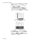

19. Second Converter Adjustments
Procedure
Second LO Frequency
3. Set HP
8568B
Spectrum Analyzer LINE to ON and press
and Shift Adjustments
(JNSTR
PRESET].
Note
The second LO and pilot second LO output power is typically -35
dBm or less. An HP 8447F amplifier is used in steps 1 through 26 to
amplify the LO power to a
useable
level for the counter and power
meter.
Note
1. Remove
A23
RF Converter assembly from HP
8568B
Spectrum
Analyzer. Removal and installation procedures are contained as
a repair procedure in the RF Section of the Troubleshooting and
Repair Manual, Volume 1.
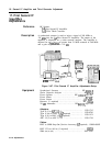
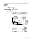
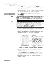
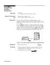
2. Position instrument on right side as shown in Figure 3-72 with the
RF Converter removed but with cables still connected.
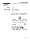
The following adjustment tools are required to adjust the
second converter:
allen
driver (08555-20121) and hex nut driver
(08555-20122). Place the
allen
driver through the center hole of the
hex nut driver. Loosen the adjustment nut using the hex nut driver
while adjusting the
bandpass
with the
allen
driver. Do not over
tighten the nut on the second converter.
4. Connect the amplifier’s input to A23A3J3 and the power meter to
the amplifier’s output.
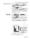
5. Adjust
A23A3
2ND
MIXER
A23A3Z4
for maximum power meter
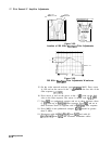
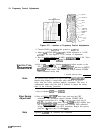
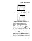
indication. See Figure 3-73 for location of adjustment.
A23
RF CONVERTER
2052 5
MHz
2ND
IF BPF
‘Zl
Z2
Z3
L2’
2HD
Ml XER
,N,‘“LD
FREO
z4
A23A3
2017.6
MHz
2NO
MIXEP
PILOT
2ND
IF BPF
Figure 3-73. Location of Second Converter Adjustments
6. Disconnect power meter and connect frequency counter to
amplifier’s output.
7. Adjust
A23A3
2ND
LO FREQ
A23A3Z9
for frequency counter
indication of 1748.6 MHz fl.O MHz. See Figure 3-73 for location
of adjustment.
8. Disconnect frequency counter and reconnect power meter to
amplifier’s output.
3-l
24 Adjustments