


4. Final Display Adjustments (SN 3004A and Above)
4. Final Display
Adjustments (SN
3004A and Above)
Reference
Description
Equipment
Procedure
Note
AlAl
Keyboard
AlA
X, Y, Z Axis Amplifiers
This procedure is used to optimize the appearance of the CRT display
during routine maintenance or after CRT replacement or minor
repairs. First, the display is adjusted for best focus over the full CRT,
then the graticule pattern is adjusted for optimum rectangular display.
Digital Photometer
........................
.Tektronix
J-16, Option 02
Photometer Probe
...................................
.Tektronix
56503
Photometer interconnect cable
............... Tektronix 012-0414-02
Photometer light
occluder
....................
.Tektronix
016-0305-00
Adjustment Procedure 2, High Voltage Adjustment (SN
3004A
and
Above) should be performed prior to performing the following
adjustment procedure.
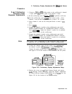
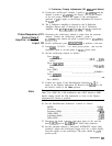
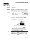
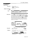
1. Connect the equipment as shown in Figure 3-31.
SPECTRUl
ANALYZER
Figure 3-31. Final Display Adjustments Setup
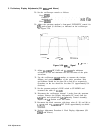
2. Set the photometer probe to NORMAL. Press
[POWER_)
on the
photometer to turn it on and allow 30 minutes warm-up. Zero the
photometer according to the manufacturer’s instructions.
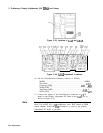
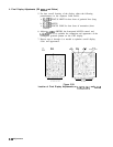
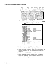
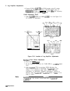
3. With the spectrum analyzer’s LINE switch set to STANDBY,
set the potentiometers listed in the
‘Iable
3-6 as indicated. See
Figure 3-32 for the location of the adjustments.
Note
In this procedure, do not adjust the following potentiometers and
variable capacitors on the
AlA
X, Y, Z Amplifier Assembly:
C104,
C109,
C204,
C209,
C307,
R117,
R217,
or
R308.
These components are
adjusted in the factory and in Adjustment Procedure 3, Preliminary
Display Adjustments (SN
3004A
and Above).
Adjustments
3.61