


2. High-Voltage Adjustment (SN 3001A and Below)
Note
The accuracy of the high-voltage probe is specified for a probe
connected to a dc voltmeter with 10
M62
input resistance. HP
3456A
and HP
3455A
digital voltmeters have a 10
MQ
input resistance on the
100 V and 1000 V ranges. All measurements in this procedure should
be performed with the DVM manually set to the 100 V range (fOO.OOO
on the HP
3456A
display).
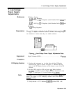
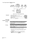
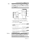
AlA
HIGH
VOLTAGE
REGULATOR
r,
P
I
,
AlA8DSl
-
AlA7TP3
.
AlA6R32
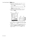
Figure 3-6. Location of High Voltage Adjustments
4. Set the LINE switch to ON. Set the front-panel INTENSITY
control fully counterclockwise (CRT beam at cut-off) to prevent
possible damage to the CRT.
5. Note the DVM indication at AlA7TP3.
DVM Indication:
6. Connect the high-voltage probe to the DVM. Connect the probe to
AlA7TP3.
7. Note the DVM indication.
DVM Indication:
8. Divide the DVM indication in step 7 by the DVM indication in
step 5. This gives the calibration factor needed to compensate for
high-voltage probe error.
Calibration Factor:
9. Disconnect the high-voltage probe from AlA7TP3. Set the
LINE switch to STANDBY. Remove the ac line cord from both
instrument sections.
Warning
The MAINS power-on indicator
AlASDSl
(red LED) should
be completely off before proceeding with this procedure. See
Figure 3-6. The indicator will remain lit for several seconds after
the ac line cord has been removed, and will go out slowly (the
light becomes dimmer until it is completely out).
Adjustments 3-3 1