


12. Time Base Adjustment (SN 2848A to 3217A05567)
The
A27A2
10 MHz Quartz Crystal Oscillator (HP P/N 1081 l-601 11)
typically reaches its specified aging rate again within 72 hours after
being switched off for a period of up to 30 days, and within 24 hours
after being switched off for a period less than 24 hours. If extreme
environmental conditions were encountered during storage or
shipment (i.e. mechanical shock, temperature extremes)
the oscillator
could require up to 30 days to achieve its specified aging rate.
Replacement oscillators are factory-adjusted after a complete warmup
and after the specified aging rate has been achieved. Readjustment
should typically not be necessary after oscillator replacement, and is
generally not recommended.
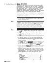
1. Set the rear-panel FREQ REFERENCE switch on
the spectrum
analyzer RF Section to INT.
Note
The + 22 Vdc STANDBY supply provides power to the heater circuit in
the
A27
10 MHz Frequency Standard assembly whenever line power
is applied to the RF Section. This allows the
A27
10 MHz Frequency
Standard oven to remain at thermal equilibrium, minimizing
frequency drift due to temperature variations. The OVEN COLD
message should typically appear on the spectrum analyzer display for
10 minutes or less after line power is first applied to the RF Section.
Note
The rear-panel FREQ REFERENCE switch enables or disables the RF
Section
+20
Vdc switched supply, which powers the oscillator circuits
in the
A27
10 MHz Frequency Standard. This switch must be set to
INT and the spectrum analyzer must be switched ON continuously
(not in STANDBY) for at least 72 hours before adjusting the frequency
of the
A27
10 MHz Frequency Standard.
2. Set the LINE switch to ON. Leave the spectrum analyzer ON
(not in STANDBY) and undisturbed for at least 48 hours to allow
the temperature and frequency of the
A27
10 MHz Frequency
Standard to stabilize.
3. Press
[ml
TRACE B (CLEAR-WRITE)
g
to turn off the display. This
prolongs CRT life while the spectrum analyzer is unattended. To
turn the CRT back on press
(SHIFT]
TRACE B (MAX HOLD)
h.
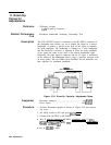
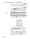
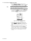
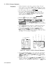
4. Connect the (Cesium Beam) Frequency Standard to the Frequency
Counter’s rear-panel
TIMEBASE
IN/OUT connector as shown in
Figure 3-54.
5. Disconnect the short jumper cable on the RF Section rear panel
from the FREQ REFERENCE INT connector. Connect this output
(FREQ REFERENCE INT) to INPUT A on the Frequency Counter.
A REF UNLOCK message should appear on the CRT display.
6. Set the Frequency Counter controls as follows:
INPUT
. . . . . . . . . . . . . . . . . . . . . . . . . . . . . . . . . . . . . . . . . . . A
ATTENUATION
. . . . . . . . . . . . . . . . . . . . . . . . . . . . . . . . .
.x10
DC Coupled
. . . . . . . . . . . . . . . . . . . . . . . . . . . . . . . . . . . . OFF
1
MR
input impedance
. . . . . . . . . . . . . . . . . . . . . . . . . . OFF
AUTO TRIG . . . . . . . . . . . . . . . . . . . . . . .
..__...........
ON
100
kHz
FILTER
. . . . . . . . . . . . . . . .
_
. . . . . . . . . . . . . . . OFF
3-100
Adjustments