


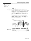

21. Slope Compensation Adjustments
Note
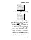
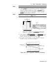
At this sweep time, some trace discontinuities are common.
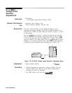
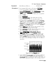
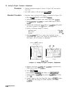
14. Adjust
A22R66
TILT for best flatness (clockwise rotation increases
the power slope), and trigger two sweeps on the synthesized
sweeper. See Figure 3-81 for the location of
A22R66.
Compare
the resultant trace with the specification. Continue adjusting
A22R66
until best flatness is achieved.
Note
Best flatness is achieved when the maximum number of frequency
points are on or near the -14 dBm reference.
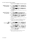
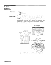
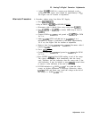
A22
FREOUENCY CONTROL
I
A
I
I/I
I
R66
TILT
Figure 3-81. Location of A22R66
TIIIT
Adjustment
15. Press TRACE A,
m,
[PEAK SEARCH], and [MARKER DELTA). Using
the data knob, place the marker on the lowest power peak. The
marker’s absolute value should be less than 2
dB.
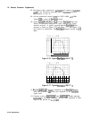
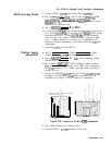
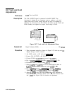
16. See Figure 3-82 for examples of typical displays of frequency
response correctly and incorrectly adjusted.
FREQUENCY RE
LIMITS
PROPERLY
MALAD.JUS
ADJi
TED
Figure 3-82. Slope Compensation Adjustment Waveforms
Adjustments 3-135