


22. Comb Generator Adjustments
Equipment
Cable, SMA (m) to SMA (m) . . . . . . . . . . . . . . . HP 85680-20094
Procedure 1.
2.
3.
4.
5.
6.
7.
8.
9.
10.
11.
12.
13.
Set instrument LINE switch to ON and press ~NSTR PRESET).
Connect CAL OUTPUT to SIGNAL INPUT 2.
Key in
CCENTER
FREQUENCY) 20 MHz, [FREQUENCY SPAN] 100 kHz,
(ATTEN)
0
dB,
LOG [ENTER
dB/DIvj
2
dB.
Adjust front-panel AMPTD CAL for signal peak at top graticule
line (-10
dBm).
Press
QNSTR
PRESET).
Key in
[SHIFT)
[RUN)
“.
This disables phase lock flags.
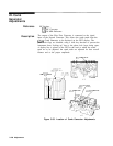
Position instrument on right side and remove bottom cover.
Disconnect cables from A23A5J2 (PILOT IF OUT) and
A23A3Jl
(1ST
IF IN) and connect a short, low-loss coaxial cable with SMA
male connectors ( do not use adapters) between A23A5J2 and
A23A3Jl.
Use coaxial cable, HP Part Number 85680-20094. If not
available, remove
A23FL2
FILTER and use between A23A5J2 and
A23A3Jl
to adjust comb generator.
Key in (START FREQ] 40 MHz. Wait for CRT annotation at lower
left of CRT display to indicate START 40 MHz.
Key in
(mFRE9)
1560 MHz. Wait for CRT annotation at lower
right of CRT display to indicate STOP 1560 MHz.
Key in [REFERENCE LEVEL] -20 dBm,
(ATTEN]
0
dB,
LOG
(ENTER
dB/DIv)
2
dB,
DISPLAY LINE
(ENTER]
-30
dBm.
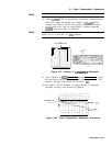
Adjust
Al6
COMB DRIVE
A16R31
for peak amplitude of CRT
trace until comb teeth begin to “wiggle.” Then adjust COMB
DRIVE
A16R31
slightly counterclockwise until the lowest comb
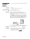
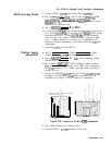
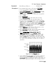
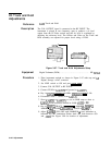
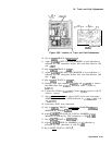
tooth (near START frequency) just begins to fall. See Figure 3-84
for a typical comb tooth display. See Figure 3-83 for location of
adjustments.
UPPER LIMIT
-22
dBm
DISPLAY LINE
AT -30
dBm
LOWER LIMIT
-36
dBm
Figure 3-84. Comb
Teeth
Display
Adjust COMB BIAS
A23A4A2R6
for peak amplitude of CRT trace
until comb teeth begin to “wiggle.
”
Then adjust COMB BIAS
A23A4A2R6
slightly counterclockwise until the lowest comb tooth
(near START) frequency) just begins to fall. See Figure 3-84 for
Adjustments
3-137