


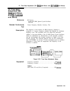

10. Step Gain and 18.4 MHz Local Oscillator Adjustments
Equipment
Digital Voltmeter (DVM)
........................ HP
3456A
Power Meter
.................................
..HP436
A
Power Sensor
.................................. HP
8481A
10 dB Step Attenuator
.............. HP
355D,
Option
H89
1
dB
Step Attenuator
............... HP
355C,
Option
H25
Procedure
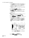
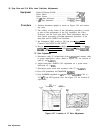
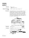
1. Position instrument upright as shown in Figure 3-46 and remove
top cover.
2. The validity of the results of this adjustment procedure is based
in part on the performance of the Log Amplifiers, the Video
Processor, and the Track and Hold. These adjustments must be
done before proceeding with the adjustment procedure of the
Step Gain and 18.4 MHz Local Oscillator.
3. Set instrument LINE switch to ON and press ~NSTR PRESET).
Connect CAL OUTPUT to RF INPUT.
4. Key
in [CENTER FREQUENCY] 20 MHz, [REFERENCE LEVEL]
-10 dBm,
(ATTEN)
0
dB,
[FREQUENCY SPAN) 0 Hz,
[-BW)
1
kHz,
l-1
100
Hz, and [SWEEP TIME) 20 ms.
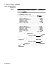
IF Gain Adjustment
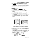
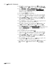
5. Disconnect cable 97 (white/violet) from
A4A8Jl
and connect cable
to power meter/power sensor. Refer to Figure 3-47 for location of
cable 97 and
A4A8Jl.
6. Adjust front-panel AMPTD CAL adjustment for a power meter
indication of -5
dBm.
7. Disconnect power meter and reconnect cable 97 to
A4A8Jl.
8. Press LIN pushbutton and MARKER
(-1.
9. Note MARKER amplitude in
mV
and adjust
A45A5R33
CAL to
70.7
mV
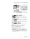
(top CRT graticule line). See Figure 3-47 for location of
adjustment.
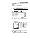
A4A7
3
MHz
BANDWI
DTH
A4A5
A4A8J
1
FILTER
STEP GAIN
R33
CAL
\-
w
A4A5
Figure 3-47. Location of IF Gain Adjustment
3-88 Adjustments