


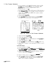

6. Video Processor Adjustments
6.
7.
8.
9.
10.
11.
12.
13.
14.
15.
16.
Set step attenuator to 120
dB.
DVM indication should be 0.000
*0.0005
V dc. (If DVM indication is out of tolerance, adjust
A4A2R79
ZERO on the log amplifier-detector board..)
Set step attenuator to 0
dB.
Key in
[Reference
LWI)
and adjust DATA knob for DVM indication as
close to + 1.000
fO.OO1
V dc as possible. (It may be necessary to
slightly adjust the front panel AMPTD CAL control to achieve
required tolerance.)
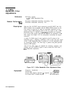
Connect DVM to A4AlTP2.
Adjust A4AlR14 OS for a DVM indication of 0.000
f0.003
Vdc.
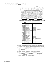
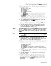
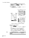
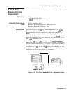
See Figure 3-36 for the location of the adjustment.
A4A1
Video
Processor
\
RI4
R36 R32
LGR20S
OS
FS
ZERO
\ \ \
I
A4A
1
Figure 3-36. Location of Video Processor Adjustments
Connect the DVM to
A4AlTP3.
Set the step attenuator to 120
dB.
Adjust A4AlR32 ZERO for a DVM indication of 0.000
rtO.001
Vdc.
Set the step attenuator to 0
dB.
Adjust A4AlR36 FS for DVM indication of
+2.000
f
0.001 V dc.
Repeat steps 12 through 15 until specifications of steps 13 and 15
are met.
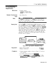
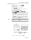
LOG Offset Adjust
17. Set step attenuator to 40
dB.
18. Key in
Cm),
(m)
I,
LOG (ENTER
dt3/mv),
(SHIFT) [ENTER
dB/DIv
q,
PREFERENCE
LEVEL] -50 dBm.
19. Connect DVM to
A4AlTPl.
Record DVM indication. Indication
should be approximately
+0.500
V dc.
V de
20. Decrease reference level to -60
dBm using the step key.
21. Adjust A4AlR2 LG OS for DVM indication of
+O.lOO
+O.OOl
V
dc greater than the DVM indication recorded in step 19. See
Figure 3-36 for location of adjustment.
3-70
Adjustments