


8. 21.4 MHz Bandwidth Filter Adjustments
Equipment
Digital Voltmeter (DVM) . . . . . . . . . . . . . . . . . . . . . . . .HP
3456A
10 dB Step Attenuator. . . . . . . . . . . . . . HP
355D,
Option
H89
1
dB
Step Attenuator. . . . . . . . . . . . . . . HP
355C,
Option
H25
Crystal Filter Bypass Network (2 required)
. . . . Refer to Figure 3-91
Procedure
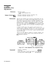
1. Position instrument upright as shown in Figure 3-40 and remove
top cover.
2. Set LINE switch to ON and press
QNSTR
PRESET].
+ 10 V Temperature Compensation Supply Check
3. Connect DVM to
A4A5TPl (+ 10 VF).
4. DVM indication should be between
+9.0
V dc and + 10.0 V dc. If
voltage is within tolerance, proceed to next step. If voltage is not
within tolerance, refer to Adjustment 10, Step Gain and 18.4 MHz
Local Oscillator Adjustments, for adjustment procedure.
A4A4
LC Adjustments
5. Set step attenuators to 0
dB.
6. Disconnect cable 97 (white/violet) from
A4A8Jl
and connect to
A4A6J
1.
7. Key in
CCENTER
FREQ] 20 MHz,
(jREs]
100 kHz, [FREQUENCY SPAN)
200 kHz, and press LIN pushbutton.
8. Press (REFERENCE LEVEL) and adjust front-panel knob to set signal
peak on screen two divisions from the top graticule.
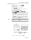
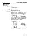
9. Adjust
A4A4C67
LC CTR and
A4A4C19
LC CTR for maximum
MARKER level as indicated by CRT annotation. See Figure
3-41
for location of adjustments. If unable to adjust LC CTR
adjustments for satisfactory signal amplitude, increase or decrease
value of
A4A4C17
and
A4A4C70.
Refer to
Table
3-3 for range of
values.
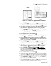
A4A4
Bnndwdth
Filte
\
c
u
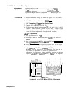
Figure 3-41.
A4A4
Location of
A4A4
21.4 MHz LC Filter Adjustments
3-78 Adjustments