


24. Track and Hold Adjustments
A6
AS ~EOM4LR ES
A6A9AlRll
CAL ADJ
I
I
10.
11.
TRIF
c29
RI1
‘LER MATCH CAL OUTPUT
RlO
A6A9Al
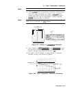
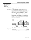
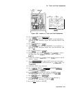
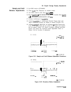
Figure 3-88. Location of Track and Hold Adjustments
Key in
m
TRACE A
[-HOLD].
b
Adjust
A3A9R44
OFFS POS until MARKER A level indication as
indicated by CRT annotation flickers back and forth between .OO
and .lO
dB.
12. Key in
cm)
TRACE A
m
d.
13. Adjust
A3A9R36
OFS NEG until MARKER A level indication as
indicated by CRT annotation flickers back and forth between .OO
and . 10
dB.
14. Key in
ISHIFT)
TRACE A
[m)
e.
15. Remove short from between A3A9TPl and
A3A9TP3
or remove
the SMB short from
A3A9Jl.
Reconnect cable 7 (violet) to
A4AlJl.
16. Connect the DVM to A4AlTP3. Connect
DVM’s
ground to the IF
section’s casting.
17. Press [REFERENCE LEVEL] and adjust DATA knob and front-panel
AMPTD CAL adjust for a DVM indication of
+2.000
fO.OO1
V dc
at A4AlTP3.
18. Disconnect DVM from instrument.
19. Key in
Cm),
TRACE A (CLEAR-WRITE], MARKER
L-1,
MARKER In], SWEEP
[CONT).
20. Adjust
A3A9R57
T/H GAIN for GAIN for MARKER A level
indication as indicated by CRT annotation of 100
*O.l
dB.
2 1.
Key in
@?i)
TRACE A
[MAX)
b.
22. Adjust
A3A9R39
GPOS for MARKER A level indication as
indicated by CRT annotation of 100 fO.l
dB.
23. Key in [SHIFT) TRACE A (VIEW)
d.
Adjustments 3-143