


17. Pilot Second IF Amplifier Adjustments
A9
PILOT
A10
PILOT
2ND
IF AMPLIFIER
3RD
CONVERTER
\
I
/
269MHz
BANDPASS
FILTER
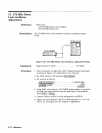
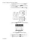
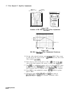
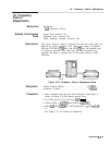
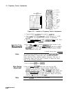
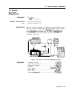
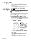
Figure 3-68.
Location of 269 MHz
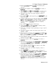
Bandpass
Filter Adjustments
3
dB
Point
>
21
MHz
-4
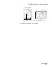
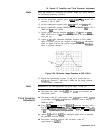
Figure 3-69.
269 MHz
Bandpass
Filter Adjustments Waveforms
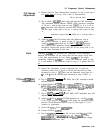
15. On the scalar network analyzer, press
[CURSOR)
MAX. Press cursor
A, ON and set the cursor to the -3
dB
point on the low side of the
filter response (fO.1
dB).
16. Press cursor A and set the cursor to the -3
dB
point on the high
side on the filter response. The cursor A should read 0
kO.1
dB.
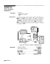
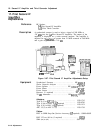
17. Press
@
on synthesized sweeper and set to three divisions down
(3
dB)
from top of
bandpass
filter response. Press
(M4)
and set to
three divisions down on opposite side of
bandpass
filter response.
18. Press MKR A on synthesized sweeper.
M3-M4
should be greater
than 21 MHz.
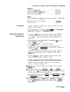
19. Disconnect cable 80
(greyblack)
from
A9Jl
and cable 81
(greybrown)
from A9J2 and reconnect instrument cables.
3-118
Adjustments