


23. Analog-To-Digital Converter Adjustments
23.
Analog-To-Digital
Converter
Adjustments
Reference
Description
Equipment
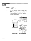
A3A8
Analog-to-Digital Converter
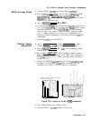
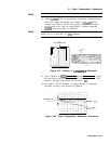
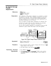
The Analog-to-Digital Ramp Converter is adjusted at zero and
full-scale by injecting a 0 V dc input and + 10 V dc input and adjusting
the OFFS and GAIN controls until the ramp output at
A3A8TPll
toggles high to low. This sets the horizontal end points for the CRT
trace display; when the sweep ramp input is at 0 V dc (the left
graticule edge), trace position 1 is set, and when the sweep ramp
input is at + 10 V
de
(the right graticule edge), trace position 1000 is
set.
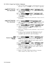
This procedure requires a + 10 V dc source which is stable and
noise-free. A simple supply circuit which can be built with common
components is illustrated in Figure 3-93. If these components are
unavailable, the alternate procedure provided below (using only the
digital voltmeter) can then be used.
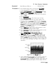
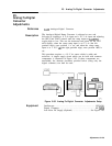
DIGITAL VOLTKTER
.-
1’
7
HP 54501A
OlGlTlZlNG
OSCILLOSCOPE
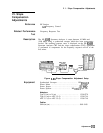
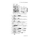
Figure 3-85. Analog-To-Digital Converter Adjustments Setup
Oscilloscope
................................................. HP 54501
Digital Voltmeter
...........................................
HP
3456A
Low-Noise DC Supply (Optional)
.....................
See Figure 3-93
Adjustments 3-139