


14. 249 MHz Phase Lock Oscillator Adjustments
Procedure
1.
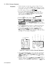
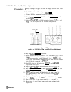
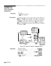
Place instrument on right side with IF-Display Section facing right
as shown in Figure 3-59.
2.
3.
4.
5.
6.
7.
8.
9.
10.
11.
Key in
[=J
2 and adjust
A7C3
for + 13.0 fO.l V dc at
A7Pl.
12.
13.
14.
adjustment.
Press 1 (RECALL 1) and adjust
A7L2
for
+5.2
rtO.05
V dc.
Repeat steps 12 and 13 until
A7C3
and
A7L2
need no further
Set LINE switch to ON and press
QNSTR
PRESET].
Connect DVM to
A7TPl
and ground to
A22TP12.
Key in [CENTER FREQUENCY) 17.6 MHz and [FREQUENCY SPAN) 0 Hz
on HP
8568B.
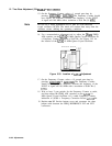
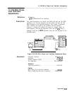
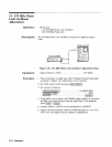
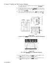
Adjust
A7
PLO
A7C3
for DVM indication between
+5.2
V dc and
+6.0
V dc. See Figure 3-60 for location of adjustment.
A7
249 MHz
PHASE LOCK OSCILLATOR
Figure 3-60.
Location of 249 MHz Phase Lock Oscillator Adjustments
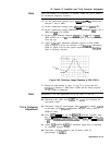
Key in
~CENTER
FREQUENCY] 37.1 MHz.
DVM indication should be between + 12.9 V dc and + 16.9 V dc. If
DVM indication is within the given range, disconnect DVM from
A7TPl and proceed to step 18. Otherwise, key in
CRAVE_)
2, SET
LINE switch to STANDBY, and place
A7
249 MHz PLO on extender
(with DVM still connected to A7TPl).
Set LINE switch to ON and key in
[RECALL_)
2 on HP
8568B
Spectrum Analyzer.
Adjust
A7
PLO
A7C3
for DVM indication of + 13.0
ho.1
V dc.
Key in [CENTER FREQUENCY) 17.6 MHz,
CFREQUENCY
SPAN] 0 Hz, and
[SAVE_)
1.
Adjust
A7
PLO
A7L2
for DVM indication of
+5.2
f0.05
V dc.
(A7L2
slug should be near center of coil form when
A7L2
is
properly adjusted.)
3-108
Adjustments