


12. Option 857 Amplitude Fidelity
Test
Equipment
Frequency Synthesizer . . . . . . . . . . . . . . . . . . . . . . . . . . . . . . . . . HP
3335A
Adapter, Type N (m) to BNC (f) . . . . . . . . . . . . . . . . . . . . . . HP 1250-0780
(2) BNC to BNC cable . . . . . . . . . . . . . . . . . . . . . . . . . . . . . . . . HP
10503A
Procedure
Log Fidelity
1.
2.
3.
4.
5.
6.
7.
8.
9.
10.
11.
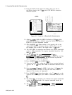
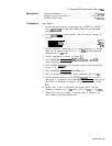
On the spectrum analyzer, connect the CAL OUTPUT to INPUT 2.
Press
IRECALL)
@
and adjust the FREQ ZERO pot for maximum
amplitude.
Press
(JNSTR
PRESET] on the analyzer. Key in analyzer settings as
follows:
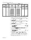
(CENTER FREQUENCY]......................................
.20 MHZ
[FREQUENCY
SPAN_)
.........................................
.50
kHz
(REFERENCE LEVEL).......................................
+ 10
dBm
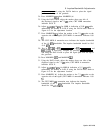
Set the frequency synthesizer for an output frequency of 20.000
MHz and an output power level of + 10
dBm. Set the amplitude
increment for 10
dB
steps.
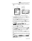
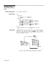
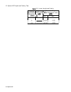
Connect equipment as shown in Figure
5-l.
Press MARKER [PEAK SEARCH),
(jMKR),
[MKR
+REF
LVL]
to
center the signal on the display.
Press SWEEP
I=)
on the spectrum analyzer and wait for the
sweep to be completed.
Press MARKER
[PEAK SEARCH), MARKER In].
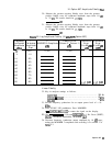
Step the frequency synthesizer output amplitude down 10
dB.
On the spectrum analyzer, press SWEEP
[ml
and wait until
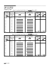
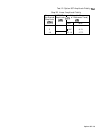
the sweep is completed. Press MARKER [PEAK SEARCH), and record
the marker A amplitude (a negative value) in column 2 of Table
5-l.
Repeat steps 8 and 9, decreasing the output power from the
frequency synthesizer in 10
dB steps from -10 dBm to -80 dBm.
Subtract the value in column 1 from the value in column 2 for
each setting to find the fidelity error.
Option 857 5-3