


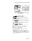

10. Step Gain and 18.4 MHz Local Oscillator Adjustments
10. Step Gain and
18.4 MHz Local
Oscillator
Adjustments
Reference
Related Performance
Tests
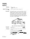
Description
IF-Display Section
A4A7
3 MHz Bandwidth Filter
A4A5
Step Gain
Resolution Bandwidth Selectivity Test
IF Gain Uncertainty Test
Center Frequency Readout Accuracy Test
First, the IF signal from the RF Section is measured with a power
meter and adjusted for proper level. Next, the 10
dB
gain steps are
adjusted by connecting the CAL OUTPUT signal through two step
attenuators to the RF INPUT and keying in the REFERENCE LEVEL
necessary to activate each of the gain steps, while compensating for
the increased gain with the step attenuators.
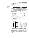
The 1 dB gain steps are checked in the same fashion as the 10
dB
gain steps, and then the variable gain is adjusted. The 18.4 MHz
oscillator frequency is adjusted to provide adequate adjustment range
of front-panel FREQ ZERO control; and last, the +
1OV
temperature
compensation supply used by the
A4A4
Bandwidth Filter and
A4A8
Attenuator-Bandwidth Filter is checked and adjusted if necessary.
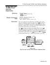
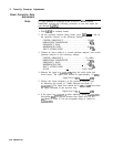
PMR
METER
1OdB
STEP 1
dB
STEP
ATTENUATOR ATTENUATOR
DIGITAL VOLTMETER
fi!&
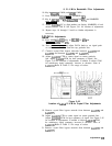
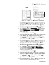
Figure 3-46.
Step Gain and 18.4 MHz Local Oscillator Adjustments Setup
Adjustments 3-87