


19. Second Converter Adjustments
Second Converter
27. Key in
m
(JJ)
T,
[FREQUENCY SPAN] 0 Hz.
Bandpass
Filter
Adjustments
28. On the synthesized sweeper, key in
ICF)
240 MHz,
a
50 MHz,
and
CPowerLeVel]
-
10 dBm.
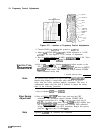
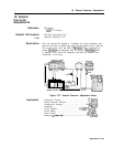
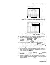
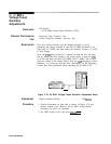
29. Connect the synthesized sweeper’s SWEEP OUTPUT (rear panel),
Z-AXIS BLANK/MKRS (rear panel), and PULSE MODULATION
INPUT (front panel) to the proper rear-panel connectors on the
scalar network analyzer as shown in Figure 3-73.
30. On the scalar network analyzer, press PRESET, turn channel 2 off,
and press
[MEAS]
(A/R).
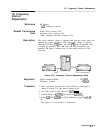
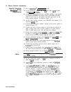
31. Connect the synthesized sweeper’s output to the power splitter as
shown in Figure 3-72.
32. Connect one arm of power splitter to scalar network analyzer R
input. Connect other arm of power splitter to A input, using a
BNC to SMB snap-on test cable and necessary adapters.
33. Set the scalar network analyzer
c-1
to 1
dB,
and set
m
(REF
LEVEL) to -16.00
dB.
Set REF POSN (press REF POSN) to the
fourth division from the bottom using the data knob.
34. On the synthesized sweeper, press
[m)
(ON), [MKR SWEEP), and
@FJ.
Set @WEEP
TIME]
to 500 ms.
35. Adjust REF LEVEL for a mid-screen response of the
bandpass
signal on the scalar network analyzer.
36. Connect the test cable from the power splitter output arm to
A23A3J2 Pilot First IF IN.
37. Connect cable 80 (gray/black) from A23A3J6 (PILOT
2ND
IF) to
the scalar network analyzer’s A input. Set
Cm]
to 10
dB/DIV.
38. On the spectrum analyzer, key in [SHIFT]
(FREERUN)V.
Note
Hold (SHIFT] in until the LED lights, then press
I-)
until the
sweep is free running.
39. On the synthesized sweeper, set
(CF)
for a frequency of 2017.6
MHz and InF] to 50 MHz.
40. Adjust
a
on the synthesized sweeper to center the
bandpass
signal.
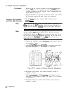
41. Adjust
A23A3
25,
Z6,
27,
and
L4
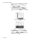
for best
bandpass
shape and
flatness at maximum amplitude of signal displayed on Scalar
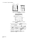
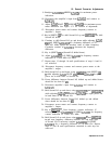
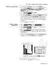
network analyzer. A typical properly-adjusted
bandpass
filter
response is shown in Figure 3-74. See Figure 3-73 for location
of adjustments. The
bandpass
filter response at the 3
dB
points
should be
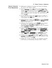
222
MHz. See Figure 3-74 and Figure 3-75 for a typical
PILOT
2ND
IF
bandpass
response for a SHIFT LO
1
and a SHIFT
LO
1.
3-126 Adjustments