


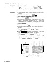

Procedure
1.
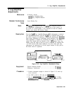
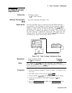
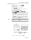
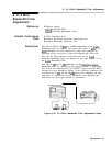
Position instrument upright as shown in Figure 3-37 and remove
top cover.
2.
Set LINE switch to ON and press ~NSTR PRESET).
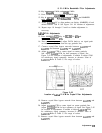
7. 3 MHz Bandwidth Filter Adjustments
Frequency Zero Check
3. Connect CAL OUTPUT signal to RF INPUT
4. Key in
IRECALL)
@.
5. Adjust front panel FREQ ZERO control for maximum signal
amplitude on the CRT display.
Filter Center and Symmetry Adjustments
6. Key in
~CENTER
FREQUENCY) 20 MHz,
CFREQUENCY
SPAN) 10
kHz,
[REsBWI)
1 kHz, and press LIN pushbutton. Press
CREFERENCE
LEVEL] and adjust reference level, using step keys and
front-panel knob to place signal peak near top CRT graticule line.
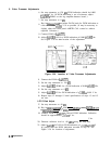
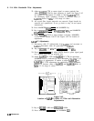
7. On the
A4A7
assembly, connect crystal filter bypass networks
between the pins above
C41
SYM,
C32
SYM,
C23
SYM, and
Cl4
SYM.
8. Adjust
A4A7C7
CTR for minimum amplitude signal peak. Adjust
A4A7C6
SYM for best symmetry of signal. Repeat adjustments to
ensure that the signal is
nulled
and adjusted for best symmetry.
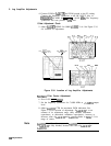
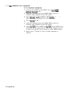
See Figure 3-38 for location of adjustments.
Note
You may find it helpful to widen and narrow the frequency span of
the instrument to adjust the
bandpass
symmetry and centering for
each filter stage.
A4A7
3
MHz
Bandwidth Filter
A4A7
Figure 3-38.
Location of Center, Symmetry, and 10
Hz
Amplitude
Adjustments
9. Remove crystal filter bypass network near
Cl4
SYM.
Adjustments 3-73