


14. 249 MHz Phase Lock Oscillator Adjustments
14. 249 MHz Phase
Lock Oscillator
Adjustments
Reference
Description
Equipment
RF Section:
A7
249 MHz Phase Lock Oscillator
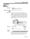
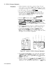
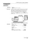
Two center frequencies are chosen: one which will tune the 249 MHz
Oscillator to its low-end frequency and one which will tune the 249
MHz Oscillator to the high-end frequency. The voltage is monitored
with a DVM at the output of the oscillator, and the oscillator
frequency is adjusted to produce the proper dc voltage output for
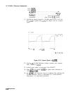
each frequency (low-end and high-end). Next, the 500 kHz Trap is
adjusted to null the 500 kHz sidebands using the sixth harmonic of the
249 MHz signal.
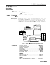
SPECTRLM
ANALYZER
DIGITAL VOLTMETER
SPECTRUM ANALYZER
1
J
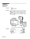
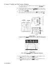
Figure 3-59. 249 MHz Phase Lock Oscillator Adjustments Setup
Spectrum Analyzer
.........................
HP
8566A/B
Amplifier
...................................... HP 8447F
Digital Voltmeter (DVM)
........................
HP
3456A
Tee, SMB Male
............................. HP 1250-0670
Adapters:
Type N (m) to BNC (f) . . . . . . . . . . . . . . . . . . . . . . . . .
1250-1250
Cables:
BNC cable, 122 cm (48 in) (2 required) . . . . . . . . . . . .
10503A
BNC to SMB Snap-On cable (2 required) . . . . . . 85680-60093
Adjustments
3-107