


8. Frequency Response Test
Note
Equipment listed is for three test setups, Figure 2-11, Figure 2-13, and
Figure 2-15.
Equipment
Synthesized Sweeper .......................................
HP
8340A
Power Meter
...............................................
..HP436
A
Power Sensor
...............................................
HP
8482A
Frequency Synthesizer .....................................
HP
3335A
Function Generator ........................................
HP
3312A
Power Splitter
.............................................
HP
11667A
Adapter, Type N (m) to BNC (f) ........................
HP 1250-0780
Adapter, Type N (m) to BNC (m) .......................
HP 1250-0082
Adapter, Type N (m) to Type N (m)
....................
HP 1250-0778
Adapter, Type N (m) to SMA (f)
........................
HP 1250-1250
Adapter, APC-3.5 (f) to APC-3.5 (f)
....................
HP 1250-1749
Cable, SMA Connectors ................................
HP 5061-5458
Additional Equipment for Option 001:
5OfY700
Minimum Loss Pad ...............................
HP
11852A
Adapter, Type N (f) to BNC (m) (7561)
..................
HP 1250-1534
Procedure
20 MHz to 1.5
GHz
1.
2.
3.
4.
Depress RANGE HOLD button on power meter.
5.
Select METER leveling on synthesized sweeper.
6.
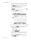
Key in the following spectrum analyzer settings:
Press ~NSTR PRESET) on spectrum analyzer and synthesized
sweeper.
Set controls as follows:
Power Meter
MODE
. . . . . dBm
RANGE HOLD
. . . OFF
CAL FACTOR %
. . . 100
Synthesized Sweeper
START FREQ
...........................................
20 MHz
STOP FREQ
............................................
1.5
GHz
SWEEP
.................................................
[-)
SWEEP TIME
.............................................
120 s
POWER LEVEL
......................................
0.00 dBm
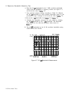
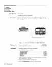
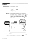
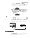
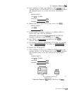
Connect equipment as shown in Figure
2-l
1. The RECORDER
OUTPUT on rear panel of power meter is connected to LEVELING
EXT INPUT of the synthesized sweeper. One output arm of the
power splitter is connected directly to SIGNAL INPUT 2 of the
spectrum analyzer via the N-to-N adapter. The power sensor
connects directly to the other splitter output.
[CENTER FREQUENCY)
......................................
.20
MHZ
FREQUENCY SPAN]
km)
............................................................................................
10
MHz
.3
MHz
Performance Tests
2.23