


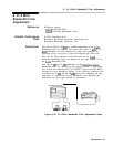

8. 21.4 MHz Bandwidth Filter Adjustments
45.
LC
46.
47.
48.
49.
50.
51.
52.
53.
54.
55.
56.
57.
58.
59.
60.
61.
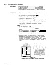
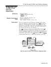
Adjust
A4ABR40
XTAL to align markers on display. MARKER
A level should indicate 1.00 X. See Figure 3-44 for location of
adjustment.
Dip Adjustments
Refer to the Resolution Bandwidth Switching Uncertainty
Performance Test, and check all bandwidth amplitudes. If
amplitude of 300 kHz bandwidth is low but amplitude of 100 kHz
and 1 MHz bandwidths are within tolerance, LC DIP adjustments
must be performed. If all bandwidth amplitudes are within
tolerance, do not perform the following adjustments.
Set LINE switch to STANDBY.
Disconnect cable 97 (white/violet) from A4ABJl and connect to
A4A6
J 1.
Remove
A4A4
Bandwidth Filter and install on extenders.
Set LINE switch to ON. Press ~NSTR PRESET).
Key in [CENTER FREQUENCY] 20 MHz,
[RES]
100
kHz,
~FREQUENCY
SPAN] 1 MHz,
[ATTEN)
0
dB,
and LOG (ENTER
dB/DIv]
2
dB.
Short
A4A4TP3
to ground.
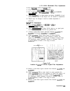
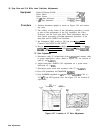
Adjust.
A4A4C41
LC DIP for minimum amplitude of signal peak.
See Figure 3-41 for location of adjustment. Key in
CPEAK
SEARCH)
MARKER
Ln],
and adjust LC DIP again to offset the signal peak
approximately -17 kHz (to the left). This is done to compensate
for the effect of placing the board on extenders. If unable to
achieve a “dip” in signal amplitude, increase or decrease value of
A4A4R16.
Refer to Table 3-3 for range of values.
Remove short, from
A4A4TP3
and short
A4A4TP8
to ground.
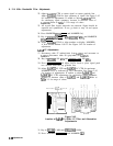
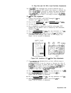
Adjust
A4A4C43
LC DIP for minimum amplitude of signal peak.
See Figure 3-41 for location of adjustment. Key in [PEAK SEARCH)
MARKER In], and adjust
C43
LC DIP again to offset the signal
peak approximately -17 kHz (to the left). If unable to achieve a
“dip” in signal amplitude, increase or decrease value of
A4A4R60.
Refer to
lhble
3-3 for range of values.
Set LINE switch to STANDBY.
Reinstall A4A4 Bandwidth Filter without extenders.
Short
A4A4TP3
and
A4A4TP8
to ground. Remove
A4A8
Attenuator-Bandwidth Filter and install on extenders. Reconnect
cable 97 to A4ABJl and reconnect cable 89 to
A4A6Jl.
Set, LINE switch to ON. Press
QNSTR
PRESET).
Key in [CENTER FREQUENCY) 20 MHz,
CRES]
100
kHz,
(FREQUENCY SPAN) 1 MHz,
[ATTEN]
0
dB,
and LOG (ENTER
dB/DIV]
2
dB.
Short
A4ABTP6
to ground.
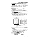
Adjust
A4ABC66
LC DIP for minimum amplitude of signal peak.
See Figure 3-43 for location of adjustment. Key in
CPEAK
SEARCH)
MARKER
@,
and adjust LC DIP again to offset the signal peak
3-82 Adjustments