


9. Impulse Bandwidth Adjustments
13. Using the DATA knob, adjust the marker down one side of
the display signal to the 7.3
dB
point; CRT MKR A annotation
indicates 0.430 X.
A4A9
IF CONTROL
\
1
1
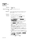
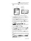
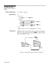
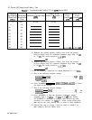
Figure 4-8. Location of Bandwidth Adjustments
14. Adjust
A4A9R61
1 MHz for MKR A indication of 500 kHz while
maintaining the marker at 0.430 X using the DATA knob. Refer to
Figure 4-8 for the adjustment location.
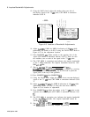
15. Press MARKER
@.
Adjust marker to the opposite side of the
signal (CRT MKR A annotation indicate 1.00 X). There are now
two markers; one on each of the signal at the 7.3
dB
point.
16. The CRT MKR A annotation now indicates the impulse bandwidth
of the 1 MHz bandwidth. The impulse bandwidth should be 1.00
MHz
fO.10
MHz.
17. Key in
(jjj
300 kHz, (FREQUENCY SPAN) 500
kHz,
CPEAK
SEARCH), and
CMKR].
If necessary, readjust by pressing
[REFERENCE LEVEL]] and using the DATA knob to place the
signal peak at the top of the graticule.
18. Press MARKER
IOFF]
then MARKER
@.
19. Using the DATA knob, adjust the marker down one the displayed
signal to the 7.3
dB
point; CRT MKR A annotation indicates 0.430
X.
20. Adjust
A4A9R62
300 kHz for MKR A indication of 150 kHz while
maintaining marker at 0.430 X using the data knob. Refer to
Figure 4-8 for location of adjustment.
21. Press MARKER
Ia].
Adjust the marker to the 7.3
dB
point on the
opposite side of the signal (CRT MKR A annotation indicates 1.00
Xl*
22. The CRT MKR A annotation now indicates the impulse bandwidth
of the 300 kHz bandwidth. The impulse bandwidth should be
300.00
h30.00
kHz.
23. Key in
@EYEiT)
10 kHz, [FREQUENCY SPAN] 20 kHz, [PEAK SEARCH),
and
C-1.
If necessary, readjust by pressing
4-28 Option 462