


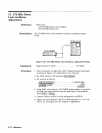

16. Second IF Amplifier and Third Converter Adjustment
14.
15.
16.
17.
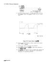
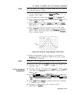
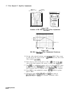
See Figure 3-65 for the typical response when the
bandpass
filter
is properly adjusted.
On the scalar network analyzer, press
@CEEQ
MAX. Press cursor
A, ON and set the cursor to the -3 dB point on the low side of the
filter response
(ho.1
dB).
Press cursor A and set the cursor to the -3
dB
point on the high
side on the filter response. The cursor A should read 0 fO.l
dB.
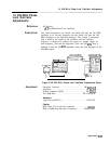
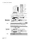
A19
2ND
A20
3RD
IF AMPLIFIER
CONVERTER
\
/
A19
Ll
AMPTD
A20
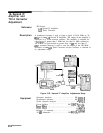
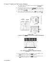
Figure 3-64.
Location of 301.4
MHz
BPF and 280 MHz AMPTD Adjustments
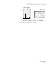
Figure 3-65.
301.4 MHz
Bandpass
Filter Adjustment Waveform
On the synthesized sweeper, press
IIv13)
and set the Marker to the
-3
dB
point on the low side of the filter response.
On the synthesized sweeper, press
(M4)
and set the Marker to the
-3 dB point on the high side of the filter response.
3-114 Adjustments