


5. Log Amplifier Adjustments
5. Log Amplifier
Adjustments
Reference
Related Performance
Tests
Note
IF-Display Section
A4A3
Log Amplifier-Filter
A4A2
Log Amplifier-Detector
Scale Fidelity Test
The
A4A3
Log Amplifier-Filter and
A4A2
Log Amplifier Detector
are temperature compensated as a matched set at the factory. In
the event of a circuit failure, a new matched set must be ordered.
Contact your nearest HP Service Center.
Description
First, the
A4A2
Log Amplifier-Detector ZERO adjustment is checked
and adjusted if necessary, then the
A4A3
Log Amplifier-Filter is set
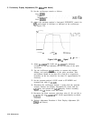
for center frequency by injecting a signal and adjusting the
bandpass
filter center adjustment for maximum DVM indication. The
bandpass
filter amplitude is adjusted by monitoring the output of the filter
control line shorted and not shorted to the +
15V
supply. Next, log
fidelity (gain and offset of the log curve) is adjusted by adjusting the
-12 VTV and the PIN diode attenuator. Last, the linear gain step
adjustments are performed to set the proper amount of step gain in
the linear mode of operation.
Equipment
Procedure
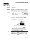
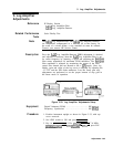
SPECTRUM ANALYZER
‘$,,,
I
DIGITAL VOLTMETER
SYNTHESIZER LEVEL
6
GENERAT
R
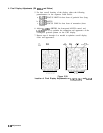
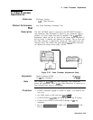
Figure 3-33. Log Amplifier Adjustments Setup
Digital Voltmeter (DVM)
........................
HP
3456A
Frequency Synthesizer
.........................
HP
3335A
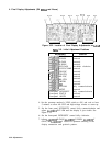
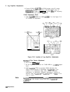
1. Position instrument upright as shown in Figure 3-33, with top
cover removed.
2. Set LINE switch to ON and press (INSTR PRESET].
3. Key in [FREQUENCY SPAN) 0 Hz,
&ENTER
FREQUENCY] 7.6 MHz,
CREFERENCE
LEVEL_)
+ 10 dBm,
[RESBW)
10 kHz, and press LIN
pushbutton.
Adjustments 3-65