


15.
16.
17.
18.
19.
20.
14. 249 MHz Phase Lock Oscillator Adjustments
Set LINE switch to STANDBY. Adjust
A7L2
one-half turn
counterclockwise before placing
A7
249 MHz PLO in HP
8568B
Spectrum Analyzer without extender. (Leave DVM connected to
A7TPl).
Set LINE switch to ON and key in
@KKK)
1. DVM indication
should be between
+5.2
V dc and
+6.0
V de.
Press 2 (RECALL 2). DVM indication should be between + 12.9 V
dc and + 16.9 V dc. Disconnect DVM from
A7TPl.
Set LINE switch to STANDBY and place
A7
249 MHz PLO on
extender.
Set LINE switch to ON, press ~NSTR PRESET), and set the analyzer
as follows:
[CENTER FREQUENCY)
........................
16.5 MHz
FREQUENCY SPAN)
L-1
..................................................................
...
0 Hz
SINGLE
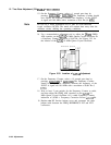
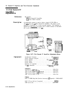
Disconnect cable from
A7Jl
and connect cable 89 (gray/white) to
one branch of a tee. Using a short coaxial cable (see Note below),
connect the other branch of the tee back to
A7Jl.
Connect the
stem of the tee to the HP
8566A/B
Spectrum Analyzer RF INPUT.
Note
The short cable 9 (white) in the IF-Display Section (A3A9J2 to
A3A2Jl)
can be disconnected and used for this adjustment. Be sure to
reconnect the cable 9 (white) when finished.
21.
Press
@?G?iG]
on the HP
8566A/B
Spectrum Analyzer and
key in (FREQUENCY SPAN) 5 MHz, [CENTER FREQUENCY) 1547 MHz,
SPEAK
SEARCH) and
t-1.
22.
On the HP
8566A/B
Spectrum Analyzer, key in [SIGNAL TRACK),
[FREQUENCY SPAN) 10 kHz,
cm)
300 Hz, [REFERENCE LEVEL)
-50 dBm, and
CATTEN]
0
dB.
23.
On the HP
8566A/B
Spectrum Analyzer, turn off [SIGNAL TRACK_]
and set
[CF
STEP SIZE) to 500 kHz on the HP
8566A/B
Spectrum
Analyzer. Press [CENTER FREQUENCY), then
a
key.
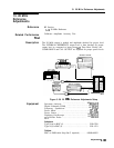
24.
Disconnect cable from the HP
8566A/B
Spectrum Analyzer RF
INPUT and connect cable (from tee) to PRE AMP input of HP
8447F
Amplifier. Connect cable from PRE AMP output to the HP
8566A/B
Spectrum Analyzer RF INPUT.
25.
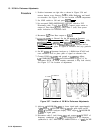
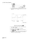
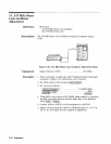
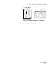
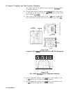
Adjust
A7
500 kHz TRAP adjustments
A7L15
and
A7L17
to null
the 500 kHz sideband displayed on the spectrum analyzer. The
500 kHz sideband should be less than -90 dBm. See Figure 3-60
for location of adjustments.
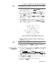
26.
27.
Press
(SAVE_)
1 on HP
8568B
Spectrum Analyzer. Set LINE switch
to STANDBY and place
A7
249 MHz PLO in HP
8568B
Spectrum
Analyzer without extender (leave tee connected).
Set LINE switch to ON and press
CRECALL)
1. Verify that 500 kHz
remains less than -90 dBm in amplitude.
28.
Disconnect tee and reconnect cable 89 (gray/white) to A7J 1.
Adjustments 3-l 09