


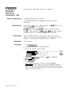

8. Frequency Response Test
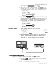
Option 001: Set [REFERENCE LEVEL] TO -6.0 dBm.
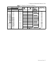
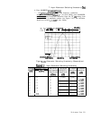
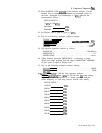
15. Repeat steps 6 through 11. Press DISPLAY LINE
[ENTER)
on the
spectrum analyzer. Use the Display Line to measure the maximum
and minimum points on the trace. Record measurements below.
SIGNAL INPUT 1
(20 MHz to 1.5
GHz)
Maximum
dBm
Minimum
dBm
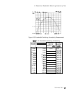
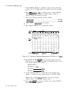
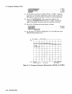
16. Press MARKER
(-1
on spectrum analyzer. Set marker to 500
MHz. Press DISPLAY LINE
(ENTER]
on the spectrum analyzer. Use
the Display Line to measure the maximum and minimum points
between 20 MHz and 500 MHz. Record measurements below.
SIGNAL INPUT 1
(20 MHz to 500
GHz)
Maximum
dBm
Minimum
dBm
100
kHz
to 20 MHz
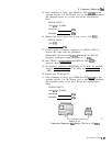
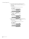
17. Set the frequency synthesizer controls as follows:
FREQUENCY
.............................................
20 MHz
SWEEP WIDTH
.........................................
19.9 MHz
AMPLITUDE
.............................................
-2 dBm
(Option 001: + 4 dBm)
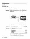
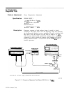
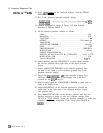
18. Connect equipment as shown in Figure 2-13. The output of the
frequency synthesizer should be connected to SIGNAL INPUT 1.
Option
001:
Use HP 11852 Minimum Loss Pad and adapters.
SPECTRUM ANALYZER
8IHIAL
I
I
#IONAL
INPUT
i
IaPuT
P
FREQUENCY SYNTHESIZER
ADAPTER
l-f
OPTIOW
001:
MO
80 oHMa/
78
ON88
PM
AW
AIDAPTUII
Figure 2-13. Frequency Response Test Setup (100
kHz
to 20 MHz)
19. Press ~NSTR PRESET) on the spectrum analyzer. Activate SIGNAL
INPUT 1 with the pushbutton.
20. Key in the following spectrum analyzer settings:
Performance Tests 2-25