


1. Low-Voltage Power Supply Adjustments
1. Low-Voltage
Power Supply
Adjustments
Reference
IF-Display Section:
AlA
f15
V Regulator
AlA
+ 120 V,
+5.2
V Regulator (Serial Number Prefix
3004A
and
above)
AlA
+ 100 V,
+5.2
V Regulator (Serial Number Prefix
3001A
and
below)
RF Section:
A24
Voltage Regulator
Description
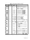
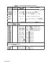
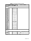
The + 15 V supply is adjusted for the IF-display Section, and the
+20
V supply is adjusted for the RF Section. All other low-voltage supplies
are measured to ensure that they are within tolerance.
SPECTRUM ANALYZER
DIGITAL VOLTMTER
ADAPTER
(+)
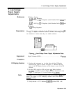
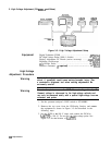
Figure
3-l.
Low-Voltage Power Supply Adjustments Setup
Equipment
Digital Voltmeter (DVM) . . . . . . . . . . . . . . . . . . . . . . . . . . . . . . HP
3456A
Procedure
IF-Display Section
1. Position the instrument on its right side with the IF-Display
Section facing right, as shown in Figure 3-1. Remove the top
cover of the IF-Display Section and the bottom cover of the RF
Section.
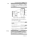
2. Set the LINE switch to ON and press
(Ip).
Mains indicator
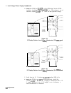
AlABDSl (red LED) in the IF-Display Section should be lit. See
Figure 3-2 and Figure 3-3 for the location of
AlABDSl.
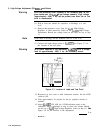
Note
Use Figure 3-2 for IF-Display Sections with serial numbers
3001A
and
below. Use Figure 3-3 for IF-Display Sections with serial numbers
3004A
and above.
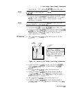
3. Verify that the + 15 V indicator AlAGDSl (yellow LED) is lit.
Adjustments 3-25