


4. Resolution Bandwidth Accuracy
Test
4. Resolution
Bandwidth
Accuracy Test
Related Adjustment
Specification
Description
Equipment
Procedure
(For instruments with Option 462, refer to Chapter 4.)
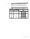
3-dB
Bandwidth Adjustments
&20%,
3 MHz
+lO%, 3 kHz to 1 MHz
&20%
10 Hz to 1 kHz
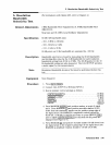
30 kHz and 100 kHz bandwidth accuracy figures apply only with
190% Relative Humidity, <
40°C.
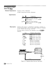
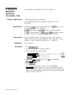
The 3
dB
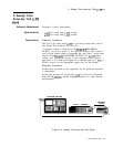
bandwidth for each resolution bandwidth setting is
measured with the MARKER function to determine bandwidth
accuracy. The CAL OUTPUT is used for a stable signal source.
None Required
1.
2.
3.
4.
5.
6.
7.
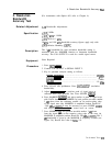
Press [INSTR PRESET).
Connect CAL OUTPUT to SIGNAL INPUT 2.
Key in spectrum analyzer setting as follows:
(CENTER FREQUENCY)
........................................
20
MHZ
FREQUENCY SPAN)
[m)
...........................................
.5
MHz
.....................................................
3 MHz
[REFERENCE LEVEL)
........................................
-10 dBm
Press SCALE LIN pushbutton. Press
csHIFT],[my
(resolution
bandwidth).
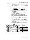
Adjust [REFERENCE LEVEL] to position peak of signal trace at
reference level (top) graticule line. Press SWEEP
[SINGLE).
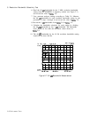
Press MARKER
[ml
and place marker at peak of signal trace
with DATA knob. Press MARKER In] and position movable marker
3
dB
down from the stationary marker on the positive-going edge
of the signal trace (the MARKER A amplitude readout should be
-3.00
dB
ho.05
dB).
It may be necessary to press SWEEP
ICONT)
and adjust [CENTER FREQUENCY) to center trace on screen.
Press MARKER
(ZJ
and position movable marker 3
dB
down
from the signal peak on the negative going edge of the trace (the
MARKER A amplitude readout should be .OO
dB
f0.05
dB).
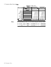
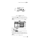
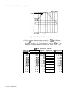
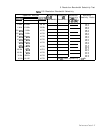
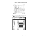
The 3
dB
bandwidth is given by the MARKER A frequency readout (see
Figure 2-6). Record this value in
Table
2-8.
Performance Tests
2-13