


6. Video Processor Adjustments
6. Video Processor
Adjustments
Reference
Related Performance
Test
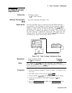
Description
IF-Display Section
A4A
1 Video Processor
Log Scale Switching Uncertainty Test
The CAL OUTPUT signal is connected to the RF INPUT through a
step attenuator. The instrument is placed in zero frequency span to
produce a dc level output from the log amplifier. The
A4A2
ZERO
adjustment, which sets the dc offset of the output buffer amplifier of
the log board, is checked and adjusted if necessary. The dc level into
the video processor is adjusted by varying the input signal level and
reference level. The offsets and gains on the
A4Al
Video Processor
are adjusted for proper levels using a DVM.
Equipment
Note
Procedure
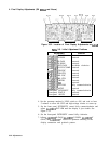
cd
0
1OdB STEP ATTENUATOR
DIGITAL VOLTMTER
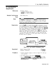
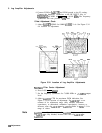
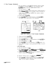
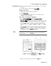
Figure 3-35. Video Processor Adjustments Setup
Digital Voltmeter (DVM)
........................
HP
3456A
10
dB
Step Attenuator
..........................
HP
355D
The voltage at
A4AlTP3
may drift noticeably with temperature
during this adjustment. Allow
A4Al
(Video Processor) to warm up at
least one-half hour prior to adjustment.
1.
2.
3.
4.
5.
Position instrument upright as shown in Figure 3-35. Remove the
top cover.
Set LINE switch to ON and press (INSTR PRESET).
Connect DVM to
A4AlTPl
and DVM ground to the IF casting.
Connect CAL OUTPUT to RF INPUT through 10
dB
step
attenuator.
Key in [CENTER FREQUENCY) 20 MHz and [FREQUENCY SPAN) 0 Hz.
Press LIN pushbutton.
Adjustments 3-69