


17. Pilot Second IF Amplifier Adjustments
Procedure
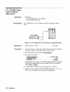
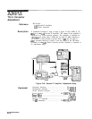
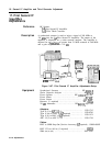
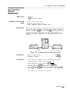
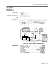
1. Position instrument on right side as shown in Figure 3-67, with
bottom cover removed.
2. Set LINE switch to ON and press
GNST
PRESET) on HP
8568B
(DUT), HP
8757A,
and HP
8340A/B.
3. Connect 20
dB
Attenuator and power splitter to RF OUTPUT of
synthesized sweeper. Connect one arm of power splitter to R
input of scalar network analyzer through detector as shown in
Figure 3-67.
4. Set synthesized sweeper FREQUENCY MARKERS
IN11)
to 254 MHz
and
lM2)
to 284 MHz.
5. Press
Icw)
269 MHz on synthesized sweeper.
6. Connect Power Meter to the other power splitter port and set
synthesized sweeper
POWER
LEVEL) for a Power Meter indication
of -20.0
ho.2
dBm.
7. Disconnect Power Meter and connect power splitter output to
A9J1, using adapter and BNC to SMB test cable.
8. Connect A9J2 to A input of scalar network analyzer through
detector, using adapter and another BNC to SMB test cable.
9. Connect synthesized sweeper SWEEP OUTPUT (rear panel),
Z-AXIS BLANK/MKRS (rear panel), and PULSE MODULATION
INPUT (front panel) to proper rear-panel connectors on scalar
network analyzer, shown in Figure 3-67.
10. On scalar network analyzer, turn channel 2 off and press
m
(A/R).
11. Set the scalar network analyzer
[SCALE_)
to 1
dB,
and set
(REF)
(REF
LEVEL) to + 10.00
dB.
Set REF POSN (press REF POSN) to the
fourth division from the bottom using the data knob.
12. On synthesized sweeper, press
(W]
(ON), [MKR SWEEP), and InF).
Set SWEEP TIME to 500 ms.
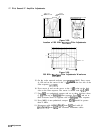
13. Adjust REF LEVEL for a mid-screen response of signal on HP
8757A.
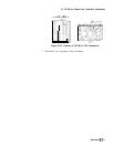
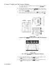
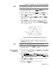
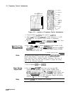
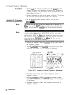
14. Adjust
A9
269 MHz
Bandpass
Filter,
A9C9,
A9Cl0, A9Cl1, and
A9C12,
for best
bandpass
filter response with gain of greater
than + 10
dB
(above REF 1 line). See Figure 3-68 for location
of adjustments. Figure 3-69 shows typical response when the
bandpass
filter is properly adjusted.
Adjustments
3-l
17